Polymerized polymeric fluid storage and purification method and system

a polymerized polymer and fluid technology, applied in the direction of liquid transfer devices, peptides, water/sewage treatment by ion exchange, etc., can solve the problems of gas storage and environmental protection, gas decomposition, and significant safety and environmental hazards of gas storage under high pressure in metal cylinders, etc., to achieve maximum storage and stabilization of fluids

Inactive Publication Date: 2011-06-07
MATHESON TRI GAS INC
View PDF26 Cites 2 Cited by
  • Summary
  • Abstract
  • Description
  • Claims
  • Application Information

AI Technical Summary

Benefits of technology

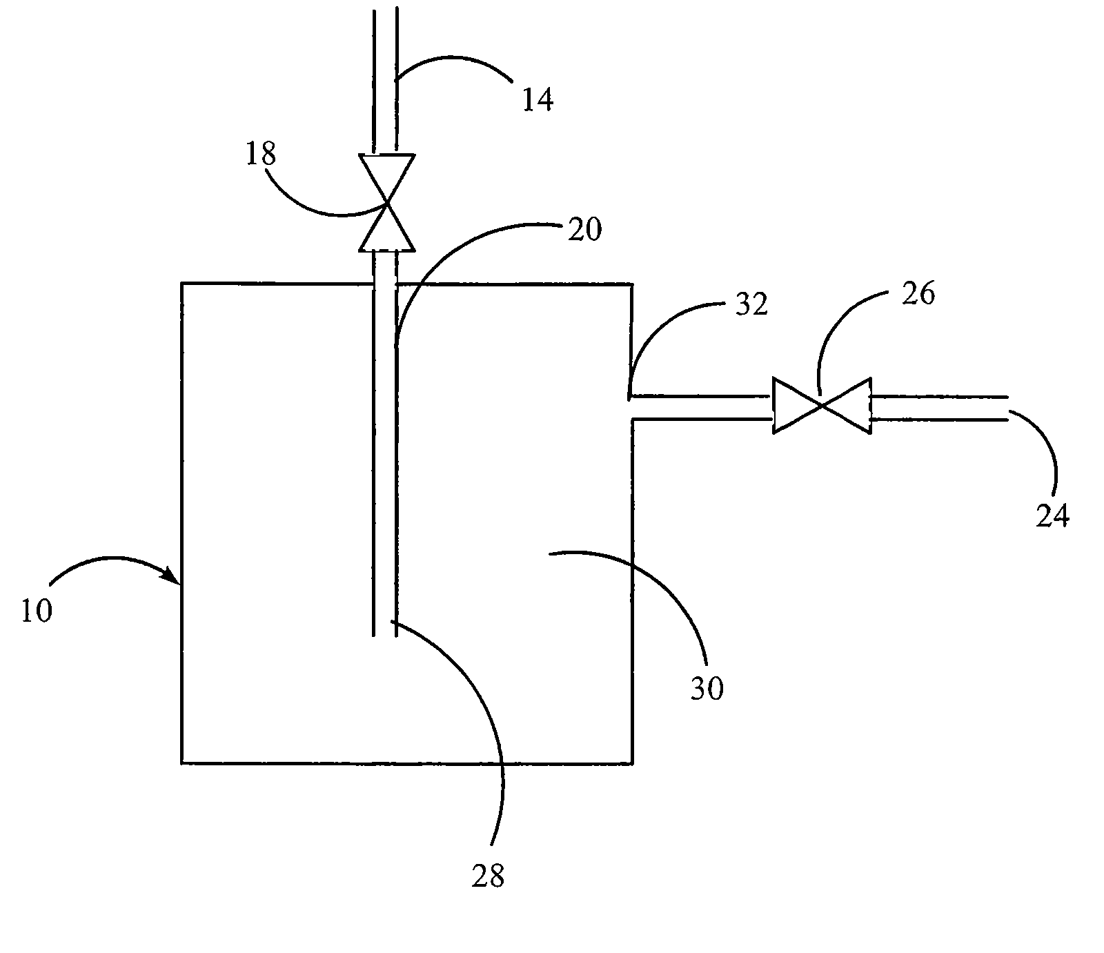
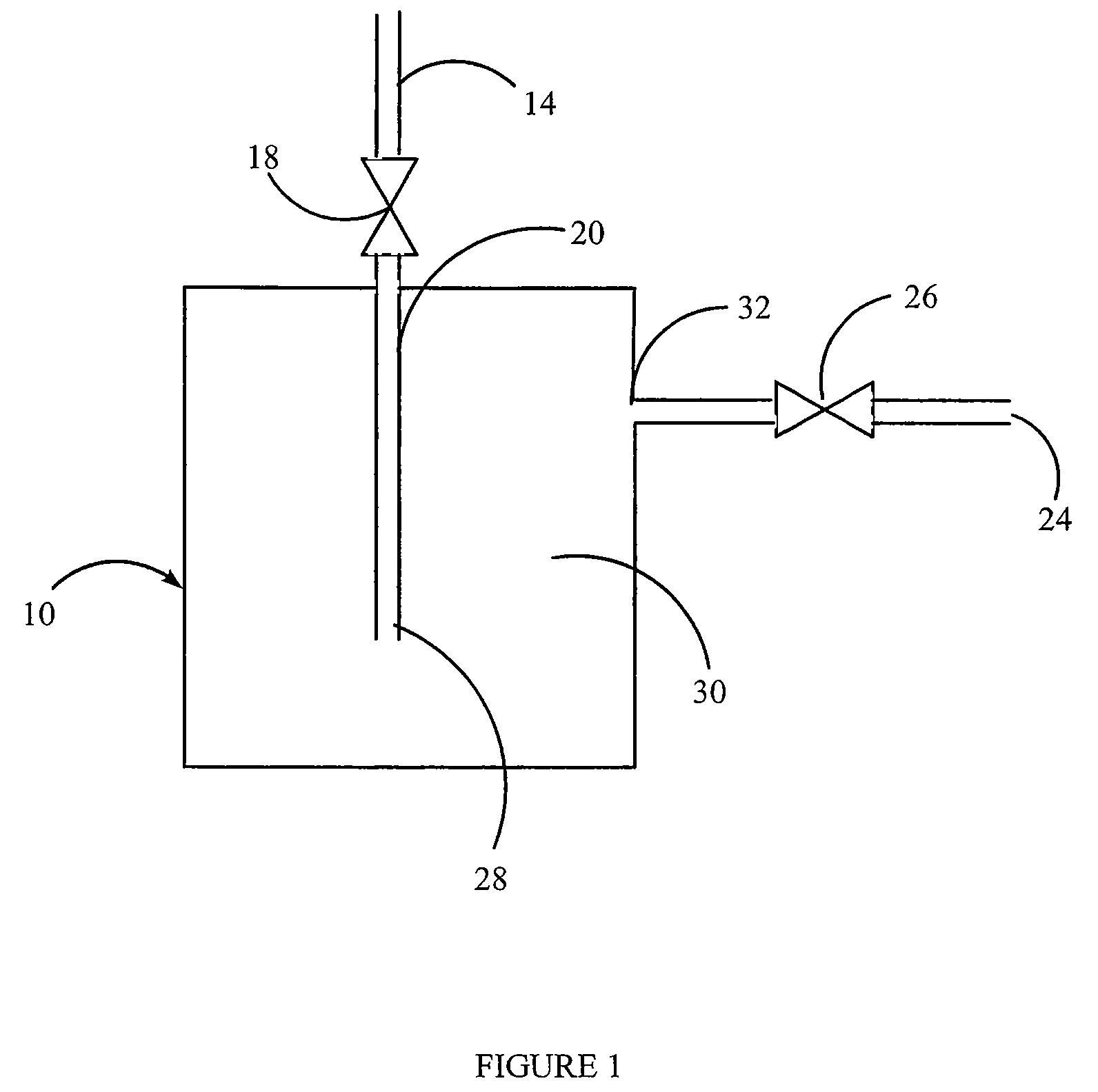
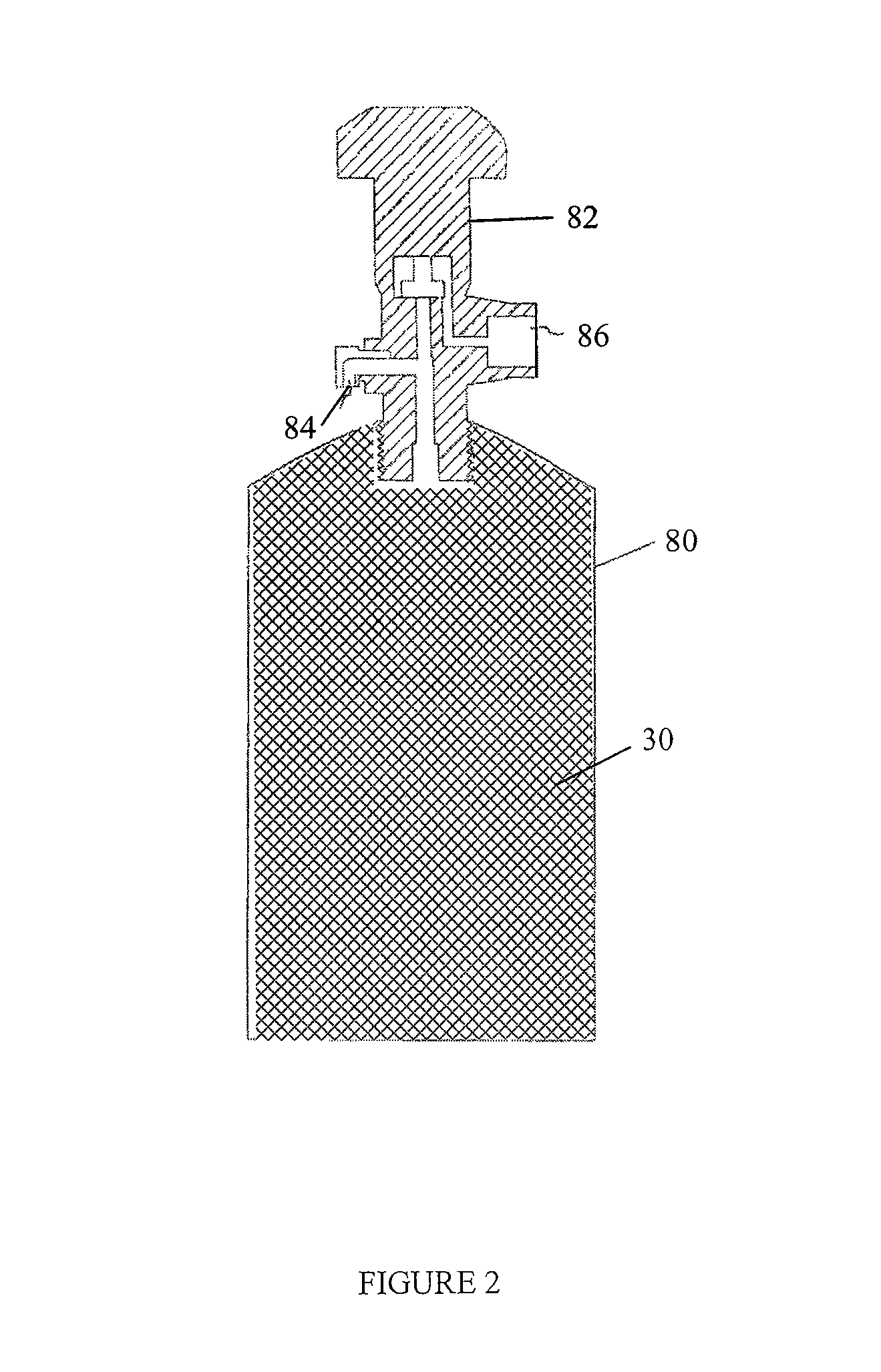
[0008]In one aspect of the invention, a method of storing and dispensing a fluid is provided. The method includes providing a vessel having a polymerized polymeric material within configured for maximized storage and stabilization of a fluid contained therein. The fluid when introduced into the vessel is contacted with the polymerized polymeric material for take-up of the fluid by the polymerized polymeric material.

Problems solved by technology

These gases pose significant safety and environmental challenges due to their high toxicity and reactivity.
Additionally, storage of hazardous gases under high pressure in metal cylinders is often unacceptable because of the possibility of developing a leak or catastrophic rupture of the cylinder, cylinder valve, or downstream component.
Additionally, some gases, such as diborane, tend to decompose when stored for a period of time.
These impurities can cause defects that reduce yields by increasing the number of rejects, which can be very expensive.
Although source gas manufacturers typically provide analyses of source gas materials delivered to the semiconductor manufacturing facility, the purity of the gases may change because of leakage into or outgassing of the containers, e.g. gas cylinders, in which the gases are packaged.
Impurity contamination may also result from improper gas cylinder changes, leaks into downstream processing equipment, or outgassing of such downstream equipment.
Furthermore, the impurity levels within the gas container may increase with length of storage time and can also change as the container is consumed by the end user.

Method used


Image

  • Polymerized polymeric fluid storage and purification method and system
  • Polymerized polymeric fluid storage and purification method and system
  • Polymerized polymeric fluid storage and purification method and system

Examples


example 1

Storage of a Gas in a Polymerized Polymeric Material—Arsine Stored in Nylon

[0115]A vessel containing nylon is prepared as described above.

[0116]The source gas, AsH3 or a gas mixture containing AsH3, is then introduced into the vessel, at 5 psig, until the uptake of AsH3 is complete. The uptake can be determined gravimetrically, or by analytical methods. For example, the concentration or absolute amount of the AsH3 can be measured at the inlet of the vessel and the outlet of the canister. AsH3 will continue to be introduced until the inlet and outlet concentrations are equivalent, indicating the nylon is saturated and cannot accept any further AsH3 under the existing conditions. At this time, the source gas flow is stopped.

[0117]The nylon-charged vessel is then heated, a pressure differential is applied, or it is sparged with an inert gas, in order to deliver the stored AsH3. The delivered gas is analyzed for AsH3 content. This can be determined gravimetrically or analytically. The t...

example 2

Storage of a Gas in a Polymerized Polymeric Material—CO2 Stored in poly[1-(4-vinylbenzyl)-3-butyl Imidazolium Tetrafluoroborate] (PVBIT)

[0118]A vessel containing PVBIT is prepared as described above.

[0119]The source gas, CO2 or a gas mixture containing CO2, is then introduced into the vessel, at 5 psig, until the uptake of CO2 is complete. The uptake can be determined gravimetrically, or by analytical methods. For example, the concentration or absolute amount of the CO2 can be measured at the inlet of the vessel and the outlet of the canister. CO2 will continue to be introduced until the inlet and outlet concentrations are equivalent, indicating the PVBIT is saturated and cannot accept any further CO2 under the existing conditions. At this time, the source gas flow is stopped.

[0120]The PVBIT-charged vessel is then heated, a pressure differential is applied, or it is sparged with an inert gas, in order to deliver the stored CO2. The delivered gas is analyzed for CO2 content. This can...

example 3

Storage and Stabilization and Purification of a Gas in a Polymerized Polymeric Material Using an Ionic Liquid Cosolvent—B2H6 Stored in poly[1-(4-vinylbenzyl)-3-butyl Imidazolium Tetrafluoroborate] (PVBIT) with 1-ethyl-3-methylimidazolium Tetrafluoroborate ([emim][BF4]) cosolvent

[0121]A vessel containing PVBIT is prepared as described above. A known amount of [emim][BF4] is added to the PVBIT-charged vessel and a vacuum bake procedure is conducted providing a PVBIT / [emim][BF4]-charged vessel.

[0122]The source gas, B2H6 or a gas mixture containing B2H6, is analyzed while by-passing the charged vessel, in order to determine the concentration of B2H6, impurities, and decomposition products. Once these concentrations in the source gas have been established, source gas is flowed into the PVBIT / [emim][BF4]-charged vessel at a pressure of 5 psig, until the uptake of B2H6 is complete. The uptake can be determined gravimetrically, or by analytical methods. For example, the concentration or abs...


PUM

PropertyMeasurementUnit
timeaaaaaaaaaa
period of timeaaaaaaaaaa
pressureaaaaaaaaaa

Abstract

A method of storing and dispensing a fluid includes providing a vessel configured for selective dispensing of the fluid therefrom. A polymerized polymeric material is provided within the vessel. The fluid is contacted with the polymerized polymeric material for take-up of the fluid by the polymerized polymeric material. The fluid is released from the polymerized polymeric material and dispensed from the vessel.

Description

BACKGROUND OF THE INVENTION[0001]1. Field of the Invention[0002]The present invention relates to a method of storing, purifying and stabilizing a fluid, and more particularly to a vessel containing a polymerized polymeric material or combinations thereof.[0003]2. Description of the State of the Art[0004]Many industrial processes require a reliable source of process gases for a wide variety of applications. Often these gases are stored in cylinders or vessels and then delivered to the process under controlled conditions from the cylinder. For example, the silicon semiconductor manufacturing industry, as well as the compound semiconductor industry, uses a number of hazardous specialty gases such as diborane, stilbene, phosphine, arsine, boron trifluoride, hydrogen chloride, and tetrafluoromethane for doping, etching, thin-film deposition, and cleaning. These gases pose significant safety and environmental challenges due to their high toxicity and reactivity. Additionally, storage of h...

Claims


Application Information

Patent Timeline
Patent Type & Authority Patents(United States)
IPC IPC(8): B01D53/04B65D81/00
CPCB01D15/00B01D53/1493B01J20/26F17C11/00B01D53/0407Y02C10/08B01D2252/30B01D2253/102B01D2253/108B01D2253/11B01D2253/202B01D2253/204B01D2257/104B01D2257/2047B01D2257/302B01D2257/404B01D2257/502B01D2257/504B01D2257/80B01D2259/4525Y02C20/40Y10S95/90
Inventor WYSE, CARRIE L.TORRES, ROBERTMILLWARD, ANDREW R.
Owner MATHESON TRI GAS INC
Why Eureka
Try Eureka