Voltage regulating systems responsive to feed-forward information from deterministic loads
a voltage regulation system and deterministic load technology, applied in the direction of electric variable regulation, process and machine control, instruments, etc., can solve the problems of loss of regulator efficiency, output voltage to recover, and deviation in output voltage that can exceed acceptable operating voltage limits, so as to improve the regulation tolerance to dynamic loading
- Summary
- Abstract
- Description
- Claims
- Application Information
AI Technical Summary
Benefits of technology
Problems solved by technology
Method used
Image
Examples
first embodiment
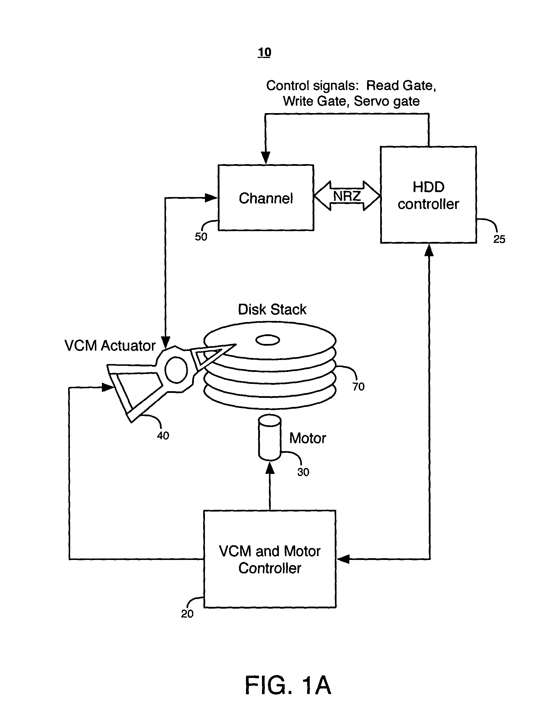
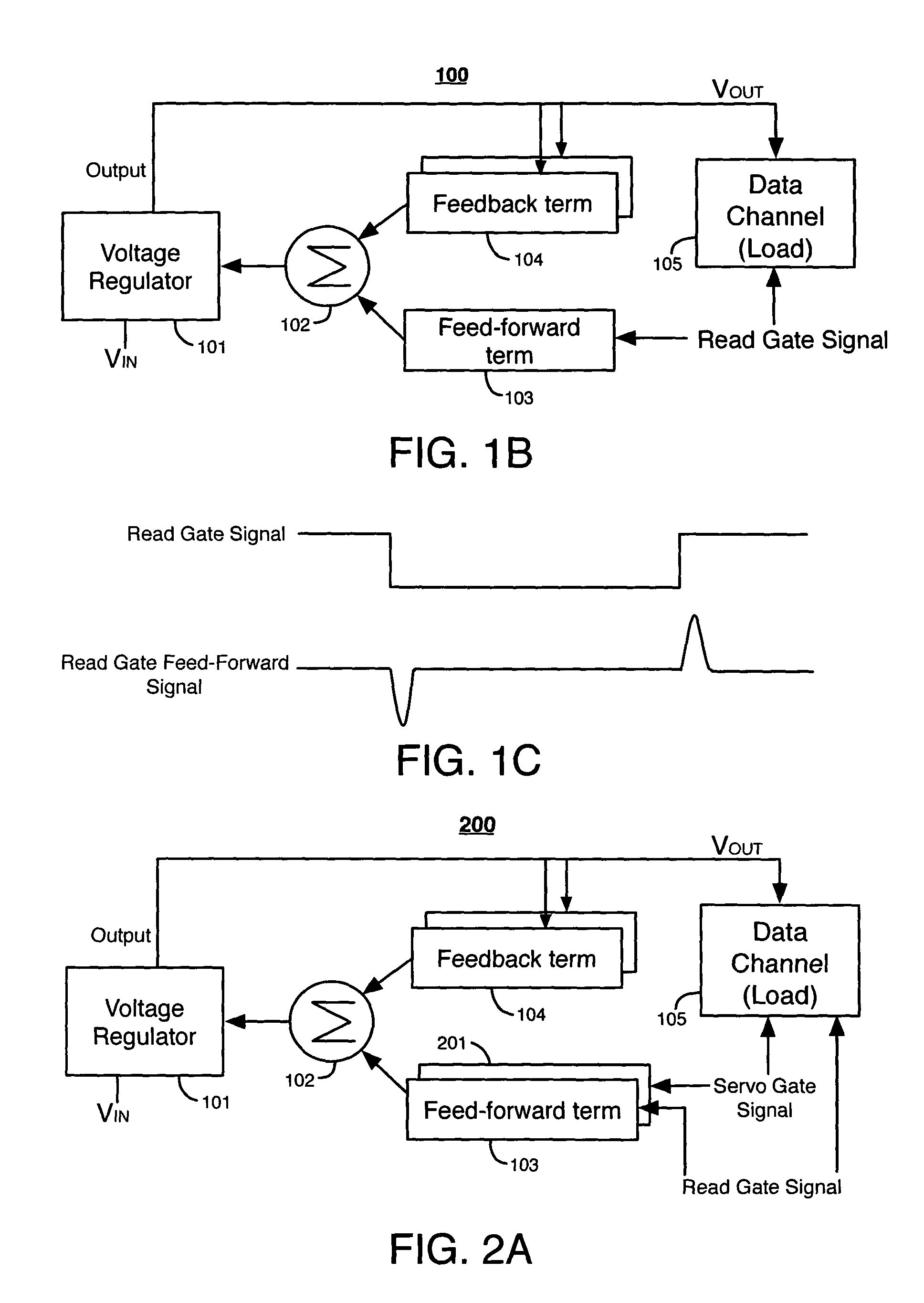
[0029]FIG. 1B illustrates a voltage regulating system 100 according to the present invention. Voltage regulating system 100 includes a voltage regulator 101, a summing node 102, a feed-forward term 103, and one or more feedback terms 104. Data channel 105 is the load in the hard disk drive that draws current from the output of the voltage regulator 101.
[0030]Voltage regulator 101 can be a synchronous switching voltage regulator, a non-synchronous switching voltage regulator, a linear voltage regulator, or any other type of voltage regulator. Voltage regulator 101 receives an input voltage VIN and provides an output voltage VOUT at its output to data channel 105. If voltage regulator 101 is a switching regulator, it typically includes an output inductor and an output capacitor for maintaining a continuous output voltage and / or current flow.
[0031]Each feedback term 104 receives a feedback signal from the output of voltage regulator 101. The feedback signal can be, for example, a volta...
second embodiment
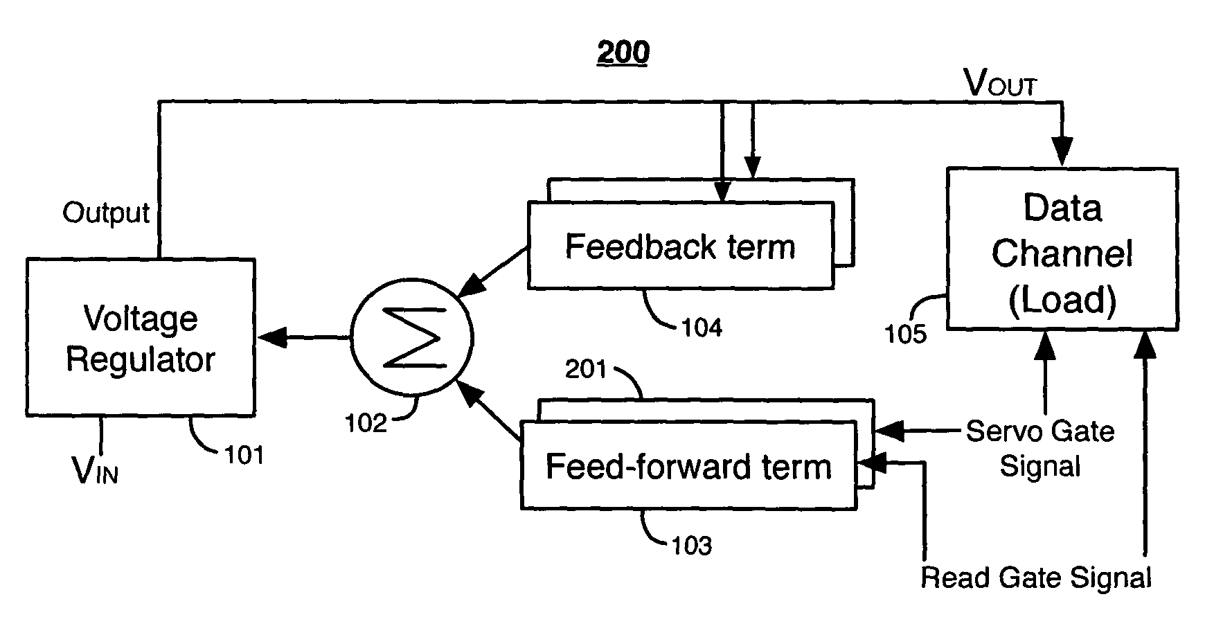
[0042]FIG. 2A illustrates a voltage regulating system 200 according to the present invention. System 200 includes all of the elements of system 100 and an additional feed-forward term 201. Feed-forward term 201 receives a servo gate signal. A servo gate signal is a signal generated by a HDD controller to cause data channel 105 to read a servo track on a hard disk.
[0043]An example of a digital servo gate signal is illustrated in FIG. 2B. Feed-forward term 201 generates the servo gate feed-forward signal in response to the servo gate signal. Rising and falling pulses in the servo gate feed-forward signal correspond to rising and falling edges, respectively, of the digital servo gate signal. The feedback control signals, the read gate feed-forward signal, and the servo gate feed-forward signal from feed-forward term 201 are summed at node 102 and then provided to regulator 101.
[0044]In the example of FIG. 2B, data channel 105 increases its load current by a predictable amount in respon...
third embodiment
[0046]FIG. 3 illustrates a voltage regulating system 300 that is responsive to feed-forward information indicative of deterministic changes in the load current, according to the present invention. Voltage regulating system 300 includes all of the elements of system 100, term selector register 301, variable weighting register 302, summing circuit 303, and hardware / software control unit 304. Voltage regulating system 300 is responsive to feed-forward signals indicative of several different deterministic events that affect the load current at load 105.
[0047]Control unit 304 can be a software-based or hardware-based system. Control unit 304 provides control signals that are indicative of deterministic changes in the load current drawn by load 105. For example, control unit 304 can provide a read gate signal, a servo gate signal, a write gate signal, etc. Control unit 304 stores the current states of these control signals in term selector register 301. For example, each storage unit in r...
PUM
 Abstract
Description
Claims
Application Information
 - R&D
- Intellectual Property
- Life Sciences
- Materials
- Tech Scout
- Unparalleled Data Quality
- Higher Quality Content
- 60% Fewer Hallucinations
Browse by: Latest US Patents, China's latest patents, Technical Efficacy Thesaurus, Application Domain, Technology Topic, Popular Technical Reports.
© 2025 PatSnap. All rights reserved.Legal|Privacy policy|Modern Slavery Act Transparency Statement|Sitemap|About US| Contact US: help@patsnap.com


