Sensor unit for the measurment of a variable in a medium

a technology of a sensor unit and a medium, applied in the field of sensor units for measuring a variable, can solve the problems of inability to miniaturize such sensors, no measurement sensors are available up to now, and the actual measurement signal is completely unacceptable, and achieves the effect of being insensitive to vibration

Inactive Publication Date: 2011-06-21
KISTLER HLDG AG
View PDF10 Cites 4 Cited by
  • Summary
  • Abstract
  • Description
  • Claims
  • Application Information

AI Technical Summary

Benefits of technology

[0020]Thus, the object of the invention is to provide a novel sensor unit, which no longer exhibits the disadvantages known from the state of the art, permits extensive miniaturization and which may be employed in particular in aggressive and / or contaminated media, is largely insensitive against vibrations, and above all may also be employed in high ambient temperatures, wherein the measurement results are not affected by temperature influences.
[0027]Thus, the construction of the sensor unit according to the present invention is significantly more simple, its susceptibility to vibrations and accelerations is almost reduced to zero and no elaborate protection of the processed chip front side by sealing measures, steel diaphragms etc. is necessary, since the sensor region, i.e. the chip front side, where the detection of the measurement variable is made is directly exposed to the medium to be measured. Since in addition no coupling medium is required, the sensor according to the present invention may also be employed in applications of high temperatures without any problems.
[0030]The chip according to the present invention may be manufactured batch wise, which immensely reduces the costs. Required for this fabrication are the materials used, in particular semiconductor materials for the base body and the measurement electronics.
[0031]In addition, the structure according to the present invention of the sensor with the electrical supply line on the back side permits a miniaturization since no supply lines have to be directed over the edge of the sensor from the front side to the electrical supply lines in the support plate which would occupy space.
[0034]It is preferable but not necessary that at the measurement opening of the sensor unit is provided a hole diaphragm. This may serve in particular to prevent the penetration of coarse dirt particles into the sensor capsule and / or to protect the sensor region of the sensor against detrimental effects, e.g. against the detrimental abrasive effects by coarse protection particles which are carried by the medium to be measured.

Problems solved by technology

A great problem in this respect is in principle the highly exact detection of the relevant measurement variables in aggressive media, in particular if the sensor in addition to the medium to be measured is also charged with external influences which have nothing to do with the actual measurement.
In this respect there frequently also arises the problem that the sensor is affected by the incorporation per se, i.e. by the contact with the machine since due to the incorporation per se a coupling between machine and sensor is built up whereby for example thermally or mechanically induced tensions are transmitted to the sensor which simulate measurement signals in the sensor due to its piezoelectric or other measurement principles while said measurement signals do not originate from said medium to be measured at all and thus falsify the actual measurement signal in a completely unacceptable manner.
Although a variety of standard sensors is well known from the state of the art, no measurement sensor is available up to now which simultaneously meets all of the properties as described above.
A significant problem of this solution resides in the fact that the possibility to miniaturize such sensors is limited due to their complicated structure, i.e. ultimately due to their operating principle.
In addition, due to reasons generally known to the person skilled in the art pressure sensors filled with liquid are not suitable for high temperature applications, in particular because due to thermal expansion effects of the coupling medium the measurement results are more and more falsified with increasing temperature and in the worst case the sensor may even be destroyed because the internal pressure that builds up in the coupling medium due to high ambient temperatures can be too high.
However, with contaminated and / or aggressive media this may lead to poor or falsified measurement results, or in the worst case to the destruction of the chip and thus of the sensor.
Due to this reason, chip coatings are frequently used with the DCE sensor which themselves have a negative effect on the properties and the entire performance of the sensor or may limit the field of application and / or the temperature range thereof.
A further dramatic disadvantage of the DCE sensors mentioned above resides in the fact that the chips, which bear the measurement electronics are contacted for the transmission of the measurement signal to an external evaluation electronics by means of a wire.
These wire connections or wire contacts, respectively, to contact the chip are in particular very sensitive to vibration and, therefore a frequent cause of failure in environments where vibration prevails, such as e.g. in internal combustion engines or in turbines.
In addition, the miniaturization potential is limited by these wire connections.
However, the disadvantage of this construction is that the medium further affects the processed chip front side and therefore the chip is not protected against aggressive media or has to be protected by an appropriate coating whereby the latter is associated with the disadvantages already described in detail above.
The disadvantages of this construction are the very difficult manufacture, a manufacture in the wafer size is e.g. not possible, and the enormous high requirements regarding the chip seal, that means regarding the medium separation, which is usually achieved via a support chip between sensor chip and feedthrough, and regarding the long term stability of the sensor in total.
Also in this case, however, the chip front side must be arranged in the sensor housing as described above and the construction is correspondingly limited with respect to the miniaturization.
For sensory applications, such constructions have the following known disadvantages: They do not have miniaturization potential, a deep sensitivity as well as no possibility of batch fabrication.

Method used


Image

  • Sensor unit for the measurment of a variable in a medium
  • Sensor unit for the measurment of a variable in a medium
  • Sensor unit for the measurment of a variable in a medium

Examples


Embodiment Construction

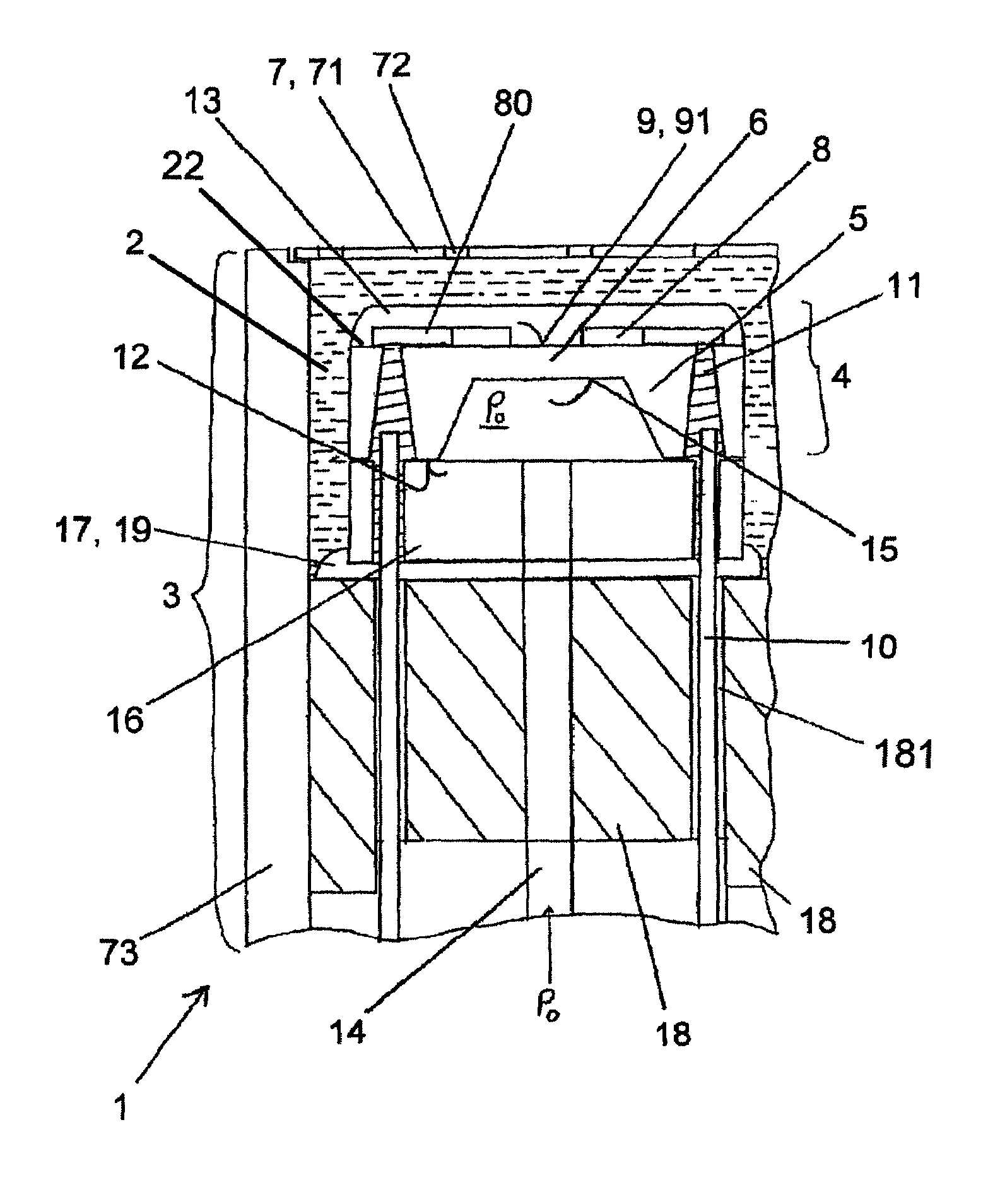
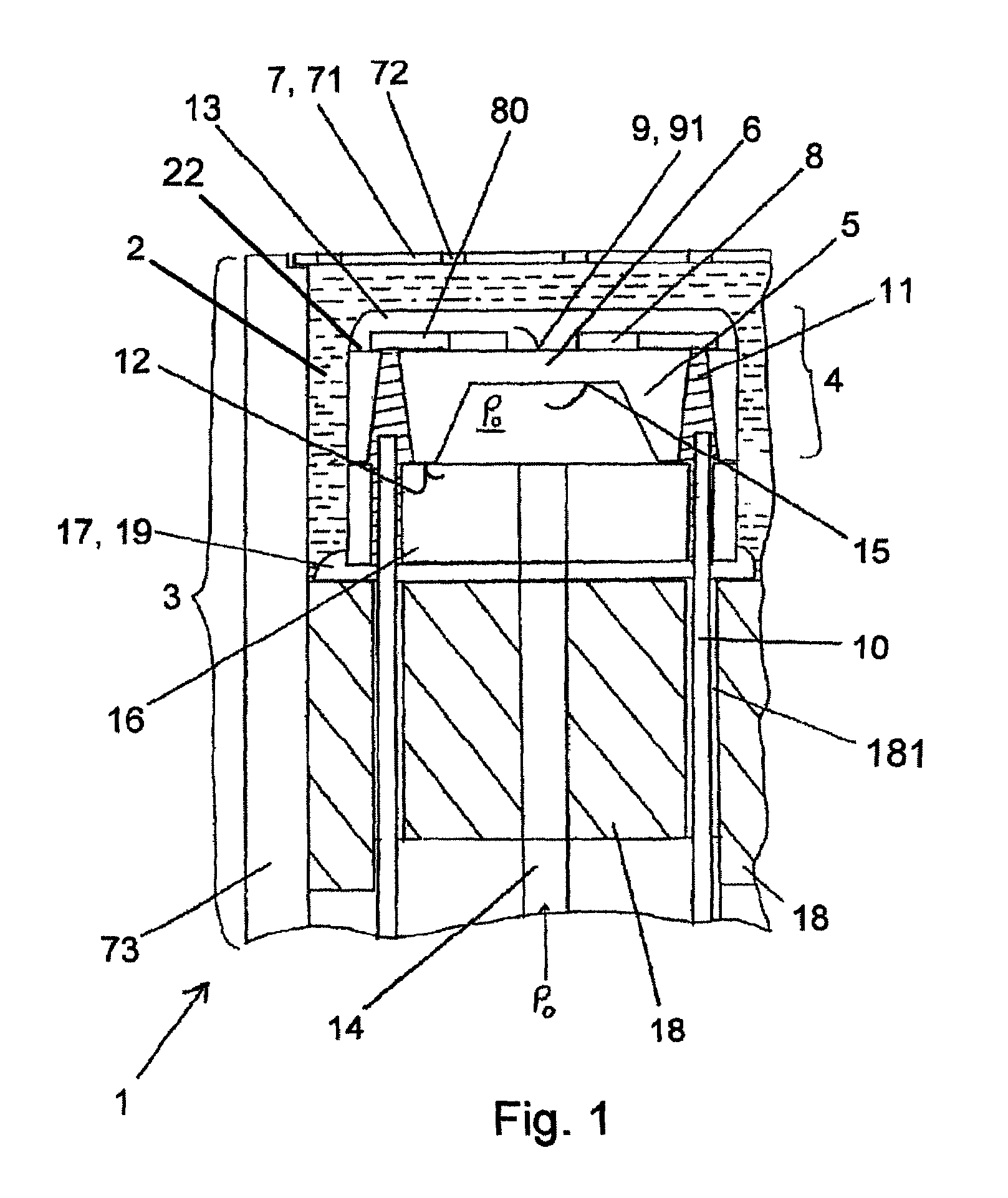
[0066]FIG. 1 shows in a schematic representation an embodiment of a sensor unit according to the present invention, partly in section, which in the following as a whole is designated with the reference numeral 1.

[0067]The sensor unit 1 which is particularly suitable for the measurement of a measurement variable in an aggressive medium 2 comprises a sensor capsule 3 in which a sensor 4 which in the example illustrated is made from SOI is arranged for the detection of a measurement variable in the aggressive medium 2. The sensor unit 1 may be used for example for the measurement of a pressure and / or temperature of the engine oil in an internal combustion engine or of a pressure and / or temperature of the gas in a turbine.

[0068]In the present case of FIG. 1 there is shown a simple pressure sensor for the measurement of the oil pressure in an internal combustion engine. The sensor 4 comprises a sensor support 16 which in the present case is a sensor support 16 made of glass, i.e. a glass...


PUM

PropertyMeasurementUnit
temperatureaaaaaaaaaa

Abstract

A sensor unit for measuring a measurement variable in a medium, in particular in an aggressive liquid or gaseous medium, comprises a sensor that is arranged in a sensor capsule and has a sensor region that is arranged on a base body. In order to detect the measurement variable in the sensor region, a measurement opening is provided in the sensor capsule. On a side facing the measurement opening, the sensor region has a measurement surface that is provided with measurement electronics. An electrical supply line is provided on the sensor for the purpose of transmitting a sensor signal that is generated by the measurement electronics. A plated-through hole is provided in the base body. The plated-through hole is used to connect the measurement electronics to the electrical supply line via signals through the base body, on a base side of the sensor that faces away from the measurement opening.

Description

CROSS-REFERENCE TO RELATED APPLICATIONS[0001]This application claims priority to Swiss Application No. 1391 / 06 filed Aug. 30, 2006, and International Application Serial No. PCT / CH2007 / 000421 filed Aug. 28, 2007.TECHNICAL FIELD[0002]The present invention relates to a sensor unit for measuring a measurement variable, in particular in an aggressive medium, a sensor having a sensor unit according to the present invention, as well as an internal combustion engine, a hydraulic or pneumatic tool and an air conditioning device having a sensor unit or a sensor according to the present invention.STATE OF THE ART[0003]In the state of the art, a variety of different sensors for the measurement of the most different measurement variables is known. In this context, sensors which detect temperature and pressure data from machines or tools for example, in order to monitor certain operating conditions or to control or regulate these devices, become more and more important. A great problem in this re...

Claims


Application Information

Patent Timeline
Patent Type & Authority Patents(United States)
IPC IPC(8): G01M15/00
CPCG01L9/0042G01L19/0069G01L19/0061
Inventor OBERMEIER, ERNSTMUKHOPADHYAY, BISWAJITVON BERG, JOCHENALBICKER, ULRICHGNIELKA, MARCOCAVALLONI, CLAUDIO
Owner KISTLER HLDG AG
Why Eureka
Try Eureka