Universal LED testing device

a technology of led testing and led light, applied in the direction of optical radiation measurement, instruments, spectrometry/spectrophotometry/monochromators, etc., can solve the problems of limited physical access to leds, significant constraints on optical test solutions, and limited time available, so as to achieve accurate testing and wide dynamic range

Active Publication Date: 2011-06-21
OPTOMISTIC PRODS
View PDF2 Cites 19 Cited by
  • Summary
  • Abstract
  • Description
  • Claims
  • Application Information

AI Technical Summary

Benefits of technology

[0011]In brief summary, the present invention provides an apparatus for optically testing LEDs or other light-emitting components in a wide variety of test environments and to whatever degree necessary pertinent to the types of faults encountered. In one embodiment, the present invention includes one or more fiber optic probes coupled to a very small multi-mode sensor unit, including a photo-sensor coupled to a processor which may be programmed to provide a variety of test modes including simple on / off testing, color determination, color matching, wavelength and relative intensity among others. The multi-mode sensor unit operates over a wide dynamic range and is capable of accurately testing LEDs that may be very dim to very bright without adjustment.

Problems solved by technology

In contrast, in other test environments such as mass-production components, assembled printed circuit boards or embedded finished products, there is often extremely limited physical access to the LEDs.
Further, the degree of optical testing required and the limited time available for testing often present significant constraints on an optical test solution.
Another constraint on an optical test solution arises from the wide range of luminous intensities produced by present day LEDs.
Another significant constraint on an optical test solution is the high density of closely spaced components found on assembled printed circuit boards.
Such close component spacing presents a challenge in terms of preventing interference from light emitted by LEDs that are adjacent to a particular LED under test.
Yet another significant constraint on an optical test solution is the supply voltage necessary to power the sensor.
Thus, a sensor intended for consumer electronics applications and designed to operate from a supply of 5 volts DC is likely to be seriously, if not irreparably, damaged should it be inadvertently exposed to the much higher supply voltages used in other applications, or the polarity of the supply reversed.

Method used


Image

  • Universal LED testing device
  • Universal LED testing device
  • Universal LED testing device

Examples


Embodiment Construction

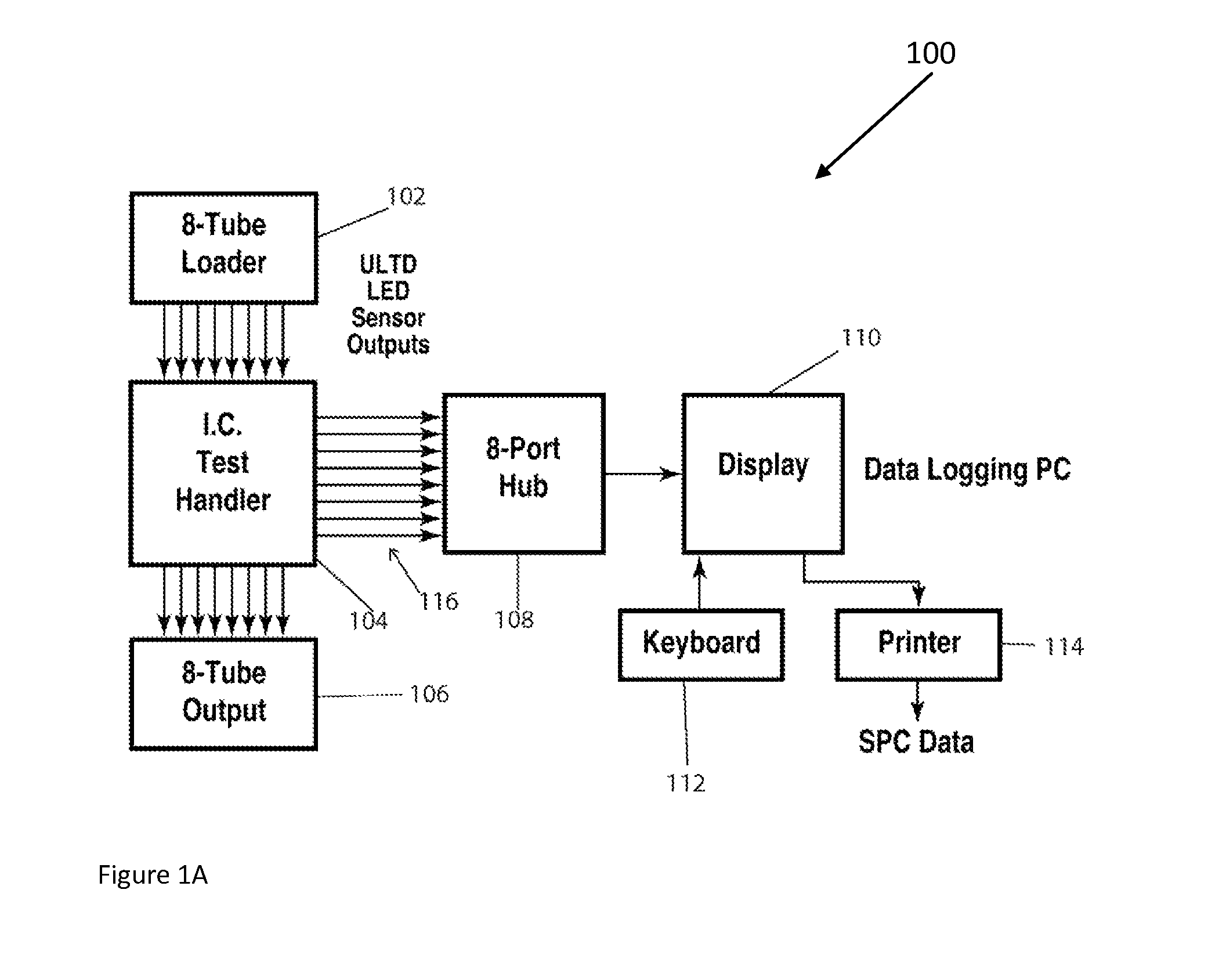
[0025]FIG. 1A shows a test environment 100 in which an integrated circuit (IC) component handler 104 receives components to be tested from an 8-tube loader 102. Handler 104 may represent a handler such as those sold by Aetrium Incorporated or any of a number of other vendors. Components for which testing is complete are returned to an 8-tube unloader or output 106. In order to perform desired optical tests on components passing through handler 104, an apparatus constructed in accordance with the present invention and described below, may be incorporated in handler 104. When so incorporated, output signals 116 which represent the results of optical tests performed within handler 104 are passed to an 8-port hub 108. Hub 108 effectively multiplexes output signals 116 to a data logging personal computer (PC) 110 which is coupled to a keyboard 112 and printer 114. A software application (not shown) running on data logging PC 110 may be used to process, record, display or print informatio...


PUM


Abstract

Apparatus for optically testing LEDs or other light-emitting components in a wide variety of test environments and to the degree necessary pertinent to the type(s) of faults encountered. In one embodiment, the present invention includes one or more fiber optic probes coupled to a multi-mode sensor unit, incorporating a photo-sensor coupled to a processor which may be programmed to provide a variety of test modes including simple on/off testing, color determination, color matching, wavelength and relative intensity among others. An extremely high sensitivity test mode is also provided for testing LEDs which emit very low intensity light in the micro-candela range in products such as automobile/aircraft cockpit control panel lighted push-buttons for night-time viewing. The multi-mode sensor unit operates over a wide dynamic range and is capable of accurately testing LEDs that may be very dim to very bright without adjustment. In another embodiment, a voltage protection circuit is provided which enables the multi-mode sensor unit to safely operate from a supply voltage in the range of approximately 5 volts DC to approximately 40 volts DC while protecting the multi-mode sensor unit from a potentially damaging overvoltage condition. The voltage protection circuit also protects the multi-mode sensor unit against potential damage caused by reverse polarity voltage spikes, or accidental steady-state reverse polarity voltages.

Description

[0001]The present application claims the benefit of U.S. Provisional Patent Application Ser. No. 61 / 353,739, filed on Jun. 11, 2010, for a UNIVERSAL LED TESTING DEVICE, which is incorporated by reference herein.BACKGROUND OF THE INVENTION[0002]1. Field of the Invention[0003]The present invention relates generally to optical testing of light-emitting devices. More specifically, the invention relates to a test apparatus which may be used, in conjunction with automatic test equipment or other equipment, to optically test light emitting diodes (LEDs) or other light-emitting components, in a wide variety of test environments and to the degree necessary pertinent to the type(s) of faults encountered.[0004]2. Background Information[0005]Automatic test equipment (ATE) is typically used to test the electrical functions of complex devices such as, for example, printed circuit boards which may contain a variety of discrete components, integrated circuits and other devices. Printed circuit boar...

Claims


Application Information

Patent Timeline
Patent Type & Authority Patents(United States)
IPC IPC(8): H01J40/14
CPCG01J1/02G01J1/0228G01J1/04G01J1/0425G01J1/0474G01J1/32G01J1/4228G01R31/2635G01J3/513G01J2001/4252G01J1/0488
Inventor LANGLEY, FRANK J.LANGLEY, JULIET A.
Owner OPTOMISTIC PRODS
Why Eureka
Try Eureka