
Turbine cooling air centrifugal particle separator

a technology of centrifugal particle separator and turbine engine, which is applied in the direction of machines/engines, efficient propulsion technologies, liquid fuel engines, etc., can solve the problems of reducing cooling effectiveness, affecting the durability of turbine engines, and affecting the efficiency of turbine engines, so as to achieve efficient removal of particles from the air and reduce the diameter

Inactive Publication Date: 2011-06-28
HONEYWELL INT INC
View PDF19 Cites 34 Cited by
  • Summary
  • Abstract
  • Description
  • Claims
  • Application Information

AI Technical Summary

Benefits of technology

The patent describes an apparatus and method for removing particles from the airflow of a jet engine before they reach the turbine blades. The apparatus includes a particle separator structure with a side facing the engine's axis, which has a plurality of pocket dividers to collect the particles. The remaining compressed air is then forced to cool the turbine blades. The apparatus also includes optional air accelerator fins placed within the entrance cavity. The combination of moving the air through a decreasing diameter airflow path while subjecting it to a centrifugal force efficiently removes the particles from the air. The technical effect of this invention is to improve the performance and longevity of jet engines by reducing the amount of particles that damage the turbine blades.

Problems solved by technology

The injected fuel is combusted by a burner, which significantly increases the energy of the compressed air.
Ingestion of microscopic particles, e.g., dust, that is entrained in incoming engine air flow poses one of the most significant limitations to turbine engine durability.
A small portion of the engine airflow is routed through cooling passages in the turbine blades and nozzles, where accumulation of particles over time can block the cooling air flow and cover the surfaces with an insulating particle layer that reduces cooling effectiveness.
Additionally, any corrosive substances in the particles may chemically react with the base alloy at the high turbine operating temperatures, thereby corroding the surfaces.
Over time, continued particle accumulation can lead to failure of the turbine blades and vanes.
The most common symptom of such component failure is a large performance decrease, resulting in premature removal of the engine for low power output.
Occasionally, symptoms are not observed until there is a failure of the turbine with extensive secondary damage to the engine resulting high repair cost.
Many engines have no devices to mitigate the effects of particle ingestion, and rely only on engine maintenance.
These approaches are inherently expensive as they allow turbine deterioration to proceed unimpeded, resulting in frequent replacement of high-cost turbine components, and more extensive replacement of engine components in cases of catastrophic turbine failures with widespread secondary damage.
Inertial particle separators rapidly turn the engine incoming airflow at the engine air inlet, with the intent that the inertia of incoming particles causes them to continue in a straight path, being unable to negotiate the sharp turns of the main airflow into the core of the engine.
However, these separators may allow considerable amounts of the smaller particles to enter the engine core.
However, the barrier systems present a considerable resistance to the incoming air flow which reduces engine performance.
The large filter surface area needed to pass the entire engine inlet airflow without large performance decrements typically results in very large inlet hardware.
These known engine inlet particle separation systems, while reducing the rate of turbine deterioration due to particle ingestion, add considerable cost and weight to the engine.
They are bulky and are difficult to integrate the engine into the aircraft or vehicle, and pose an overall performance loss due to either the energy needed to drive the scavenge blower or the inlet pressure loss of a barrier filter.
The performance loss of an inlet particle separation system is manifested as either, or a combination of reduced power output, increased fuel consumption, and increased turbine operating temperature (which accelerates turbine deterioration).
However, enhanced dust separation over these existing devices is needed.

Method used


Image

  • Turbine cooling air centrifugal particle separator
  • Turbine cooling air centrifugal particle separator
  • Turbine cooling air centrifugal particle separator

Examples


Embodiment Construction

[0019]The following detailed description of the invention is merely exemplary in nature and is not intended to limit the invention or the application and uses of the invention. Furthermore, there is no intention to be bound by any theory presented in the preceding background of the invention or the following detailed description of the invention.

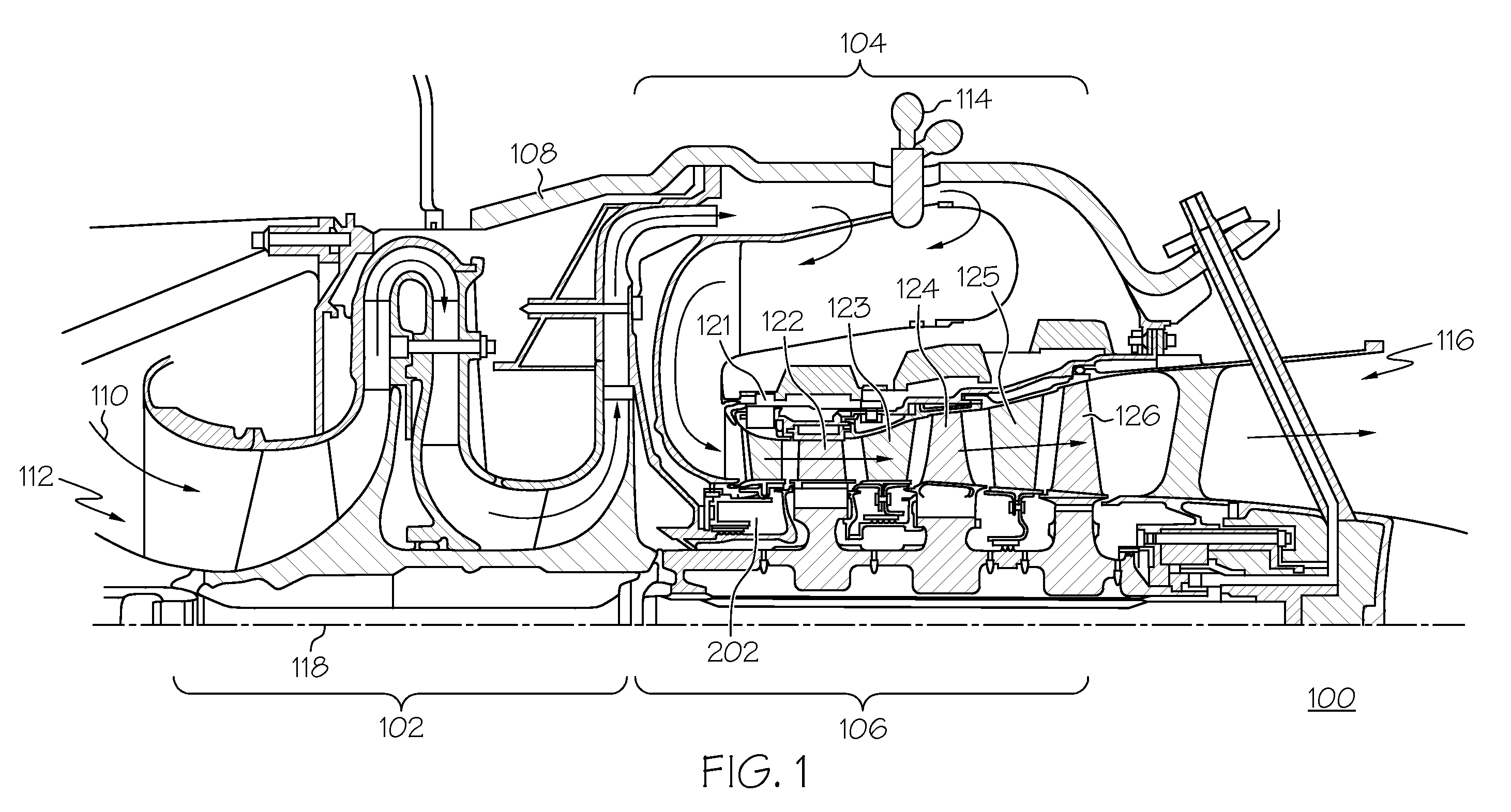
[0020]Before proceeding with a detailed description, it is to be appreciated that the described embodiment is not limited to use in conjunction with a particular type of turbine engine, or even to use in a turbine. Thus, although the present embodiment is, for convenience of explanation, depicted and described as being implemented in an auxiliary power unit (APU), it will be appreciated that it can be implemented in various other types of turbines, and in various other systems and environments.

[0021]An APU is, in most instances, a gas turbine engine that includes a compressor, a combustion system, and a turbine. During operation of the APU, ...


PUM


Abstract

A centrifugal particle separator removes particles such as dust particles from a compressed airflow prior to reaching and cooling the turbine blades of a turbine engine. A particle separator structure defines a plurality of inward-facing pockets which are separated by pocket dividers defining an airflow path having a diameter that decreases from the entrance to the exit. A centrifugal force created by the rotating centrifugal particle separator assembly causes particles to collect within the plurality of pockets and the remaining compressed air is provided to cool the turbine blades. The decreasing diameter of the airflow path forces the airflow with particles to accelerate to a rotational velocity greater than that of the rotating particle separator by conservation of momentum.

Description

FIELD OF THE INVENTION[0001]The present invention generally relates to aircraft engine rotor components and, more particularly, to a method and apparatus for removing particles such as dust from the airflow prior to cooling the turbine blades.BACKGROUND OF THE INVENTION[0002]Gas turbine engines are often used to power aircraft and to supply industrial power. A gas turbine engine includes, for example, four major sections: compressor, combustor, turbine, and exhaust.[0003]The compressor section raises the pressure of the air to a relatively high level. Compressor components such as compressor blades and impellers are primary components in this cold section for any turbine engine. The compressed air from the compressor section then enters the combustor (hot) section, where a ring of fuel nozzles injects a steady stream of fuel. The injected fuel is combusted by a burner, which significantly increases the energy of the compressed air.[0004]The high-energy compressed air from the combus...

Claims


Application Information

Patent Timeline
Patent Type & Authority Patents(United States)
IPC IPC(8): F01D25/00
CPCF01D5/081F01D25/32F02C3/08F05D2260/607Y02T50/676F05D2220/50Y02T50/673Y02T50/60
Inventor BREMER, THOMAS
Owner HONEYWELL INT INC
Learn More