Passive mode tracking through existing and future wireless networks

a wireless network and passive mode technology, applied in the field of wireless communication systems, can solve the problems of difficult to acquire a satellite signal inside cargo hold and building, difficult to change the behavior of mobile devices, and much higher signal levels, so as to reduce the effort of positioning, increase precision, and reduce the effect of unit effor

Active Publication Date: 2011-07-05
TAVENIKU MIKAEL BROR
View PDF53 Cites 51 Cited by
  • Summary
  • Abstract
  • Description
  • Claims
  • Application Information

AI Technical Summary

Benefits of technology

[0017]With this method of fall-back (actually increased precision with greater effort) the units' effort of positioning would be minimized while the precision of positioning would be available when needed or requested.
[0018]The method improves the size, weight, power consumption, and complexity of the tracking units in the field by moving most of their work onto the backend system and the networks that it attaches to. The method reduces the cost of the tracking itself by not needing to setup formal communication and data transfers over the networks, but instead use “network control” information as the information source. The method also improves the potential for much richer and more real-time tracking and health information by the vast resources that are available on the backend side of the system. The derived information to the user (or internal to the system) could even be based on a fusion of the inform

Problems solved by technology

Additionally, in some cases the mobile device may be required to change its behavior.
In many situations, it is difficult to acquire a satellite signal inside cargo holds and buildings, h

Method used


Image

  • Passive mode tracking through existing and future wireless networks
  • Passive mode tracking through existing and future wireless networks

Examples


Embodiment Construction

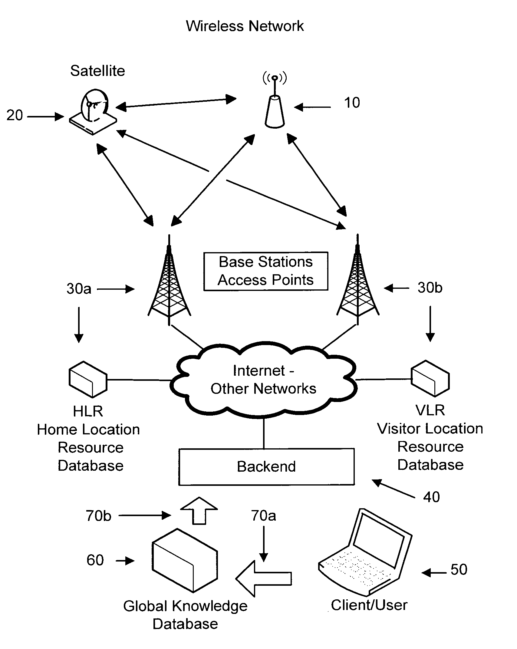
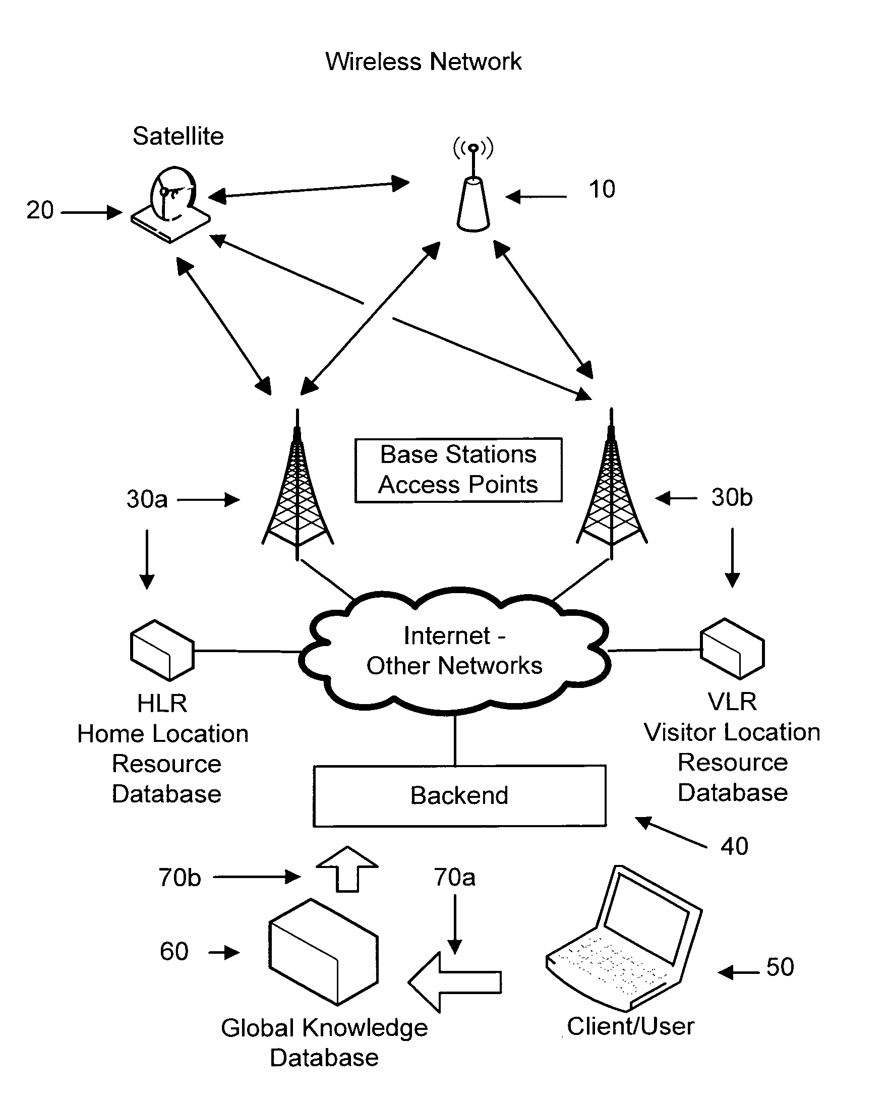
[0031]As this method conveys the tasks and communication to the backend system (40), the backend may advise the tracking unit (10) about proper behavior based on the GKD, Global Knowledge Database, (60) about the tracking units (10) location / situation. One possibility would be if there are no available networks within range for the next few hours (of estimated travel), it is no use for the unit (10) to be searching for one and the backend (40) can advise the unit (10) not to search. Regulatory or other reasons may require the tracking unit (10) to behave in a particular manner, such as at an airport or in an aircraft during flight. The backend (40), better understanding what the unit (10) should be doing, may advice the unit (10) to modify its behavior. Additional information such as Google maps can be used to determine airport location, U.P.S. schedules used for trucking, airline schedules for flights, and packet routing information could be used for hand-offs etc. Third party info...


PUM


Abstract

A method and system of Passive Mode Tracking of an item, object or cargo associated with a wireless communication device through existing and future wireless networks is described. The method builds on the observation that for many applications, cargo tracking included, an exact GPS or comparable accuracy method of location is not always necessary, however, the progress or rough movement, is. Therefore it is possible to utilize the tracking units' geographical location based on the registration process of a wireless service and its associated networks to locate the tracking unit. This method improves the size, weight, power consumption and complexity of the tracking unit by removing work from the tracking unit and utilizing the information collected by the wireless system(s) and the network(s) it attaches to. The location of the tracking unit is determined by inquiring of the wireless network the location of the wireless communication device.

Description

CROSS-REFERENCE TO RELATED APPLICATIONS[0001]This application claims the benefit of U.S. Provisional Application Ser. No. U60 / 995,040 filed Sep. 24, 2007 by the present patent applicant.FEDERALLY SPONSORED RESEARCH[0002]Not ApplicableSEQUENCE LISTING[0003]Not ApplicableFIELD OF THE INVENTION[0004]The following disclosure relates to wireless communication systems and more specifically to a power efficient method for the conservation of energy in wireless data collection and communication when tracking items, packages, cargo and other assets utilizing the infrastructure of networks.BACKGROUND OF THE INVENTION[0005]Tracking and monitoring the location, movement and health of items, objects and cargo can be done in several ways. The conventional state of the art in location tracking and telemetry is based upon the tracking unit determining its health and location by executing local tasks on the tracking unit and communicating the results, either on request or independently, based on tim...

Claims


Application Information

Patent Timeline
IPC IPC(8): H04W24/00
CPCG06Q10/0833G06Q10/087G06Q20/203G06Q20/208H04W4/02H04W64/00H04W4/029
Inventor TAVENIKU, MIKAEL BROR
Owner TAVENIKU MIKAEL BROR
Why Eureka
Try Eureka