Droplet removing device and method in plasma generator

a technology of removing device and plasma generator, which is applied in the direction of magnetic separation, vacuum evaporation coating, coating, etc., can solve the problems of loss of uniformity of thin film formed on the base member surface, defect product of thin film, and difficulty in operation, so as to achieve simplified structure of the whole droplet removing device, high purity, and easy manufacture

Active Publication Date: 2011-07-12
FERROTEC
View PDF11 Cites 5 Cited by
  • Summary
  • Abstract
  • Description
  • Claims
  • Application Information

AI Technical Summary

Benefits of technology

[0022]According to the first form of the present invention, the apertures more than one are comprised in the tubular traveling passage and the passing hole is formed in the eccentric position of this aperture. The magnetic field of which the line of magnetic force passes the eccentric passing hole in the shape of curvature is formed by said magnetic field generating means arranged on the outer circumference of said tubular traveling passage. Since said plasma is the charged particles, this plasma coils itself around the line of magnetic force and passes curvedly through the eccentric passing hole. As the droplets traveling with plasma have no charge, the droplets go straight due to their inertia when the plasma passes curvedly through the eccentric passing hole of the aperture, so that the droplets jump out in the outside and can be removed by colliding with the wall surface of the aperture. Therefore, by removing the droplets, the surface of article being processed disposed ahead of the tubular traveling passage can be treated by only the plasma in which most of the droplets do not mix. As thus described, since the surface of article being processed can be processed by only the plasma in which most of the droplets do not mix, the film of high purity can be formed on the surface of the article being processed.
[0023]In addition, because only the aperture is arranged in the tubular traveling passage, the wall surface of the aperture on which droplets bonded to and the wall surface of the tubular traveling passage can be overhauled easily, so the operation removing the bonding droplets can be easily performed. Additionally, because only the aperture is arranged in the tubular traveling passage, the structure of the whole droplet removing device can be simplified, and it is possible to manufacture the device cheaply and easily.
[0024]According to the second form of the present invention, a plurality of apertures are disposed in the tubular traveling passage, and the positions of eccentric passing holes of the apertures next to each other are arranged to be shifted each other. Therefore, the small droplets passing through the eccentric passing hole of the first step aperture with the plasma jump out in the outside due to their inertia when the plasma passes curvedly through the eccentric passing hole, and said small droplets are removed by colliding with the wall surface of the second step aperture. When the plasma passes curvedly through the third step aperture, the small droplets traveling with the plasma can be removed. As described above, by disposing the multistage apertures, the droplets traveling with the plasma can be decreased more, so that the surface of the article being processed disposed ahead of the tubular traveling passage can be treated with the plasma of higher purity. Furthermore, when the number of apertures disposed in the tubular traveling passage is increased, the number of small droplets traveling with the plasma can be decreased, so that the purity of the plasma can be raised. In addition, the eccentric passing holes of apertures next to each other can be naturally arranged to be shifted 180 degrees in the circumferential direction, and its shifted angle can be selected from arbitrary angle such as 90 degrees and 60 degrees. Additionally, the positions of the eccentric passing holes of apertures can be formed to shift in the radial direction.
[0025]According to the third form of the present invention, as the magnetic field generating means consists of the slant magnetic field generator, there is formed the slant magnetic field of which the line of magnetic force passes curvedly through the eccentric passing hole by said slant magnetic field generator. Since the slant magnetic field is formed by the slant magnetic field generator, this slant magnetic field can be freely adjusted to be matched with said eccentric passing hole of the aperture, thus the plasma stream can be certainly guided into said eccentric passing hole.
[0026]According to the fourth form of the present invention, the slant magnetic field generator is formed by said electromagnet or said permanent magnet arranged slantingly on the outer circumferential surface of the tubular traveling passage, there can be formed the slant magnetic field of which the line of magnetic force passes curvedly through the eccentric passing hole by said electromagnet or permanent magnet disposed slantingly. In the case forming the slant magnetic field by said electromagnet, the high slant magnetic field can be formed by means of increasing the number of turns of coil. Furthermore, by changing the number of turns of said coil and the coil current, the intensity of magnetic field can easily controlled to become lower or higher. In addition, the angle of the slant magnetic field can be easily adjusted or changed by changing the slant angle of said electromagnet. Furthermore, when said electromagnet is constructed by super-conducting magnet (electromagnet with coil of super-conducting wire), it is expected that there is arranged the slant magnetic field generator of which energy loss hardly exist, so the droplet removing device whose electric power consumption is hardly can be provided. Besides, in the case that the slant magnetic field is formed by the permanent magnet, by means of adjusting the direction of the permanent magnet, the slant magnetic field can be formed to match with the eccentric passing hole of the aperture. Furthermore, by using of the permanent magnet whose magnetic force is strong, it is also possible to form the high slant magnetic field. Moreover, the positions of N pole and S pole of said permanent magnet disposed on the outer circumference of the tubular traveling passage can be chosen freely, and the N pole and S pole of said permanent magnet can be easily installed.
[0027]According to the fifth form of the present invention, said slant magnetic field is formed by composition of the traveling magnetic field generated by the traveling magnetic field generator and the radial direction magnetic field generated by the radial direction magnetic field generator. This slant magnetic field is formed at the position that the line of magnetic force passes curvedly through the eccentric passing hole. By means of increasing the radial direction magnetic field, there is formed the plasma stream that can largely curve through the eccentric passing hole, so that the plasma curving largely through the eccentric passing hole can be formed. In this case, since the plasma curves largely, many small droplets traveling with said plasma jump out in the traveling direction by their inertia, so the larger amount of droplets traveling with the plasma can be removed.

Problems solved by technology

When these droplets bond to a base member surface, the uniformity of thin film formed on the base member surface is lost, and it becomes defect product of thin film.
However, there are the following problems in said magnetic filter method.
However, the operation is not easy, because the duct 102 is formed in the shape of bellows.
Furthermore, it is technically difficult to form steel materials to bellows-shaped duct 102, and besides, there is a defect to become expensive.

Method used


Image

  • Droplet removing device and method in plasma generator
  • Droplet removing device and method in plasma generator
  • Droplet removing device and method in plasma generator

Examples


first embodiment

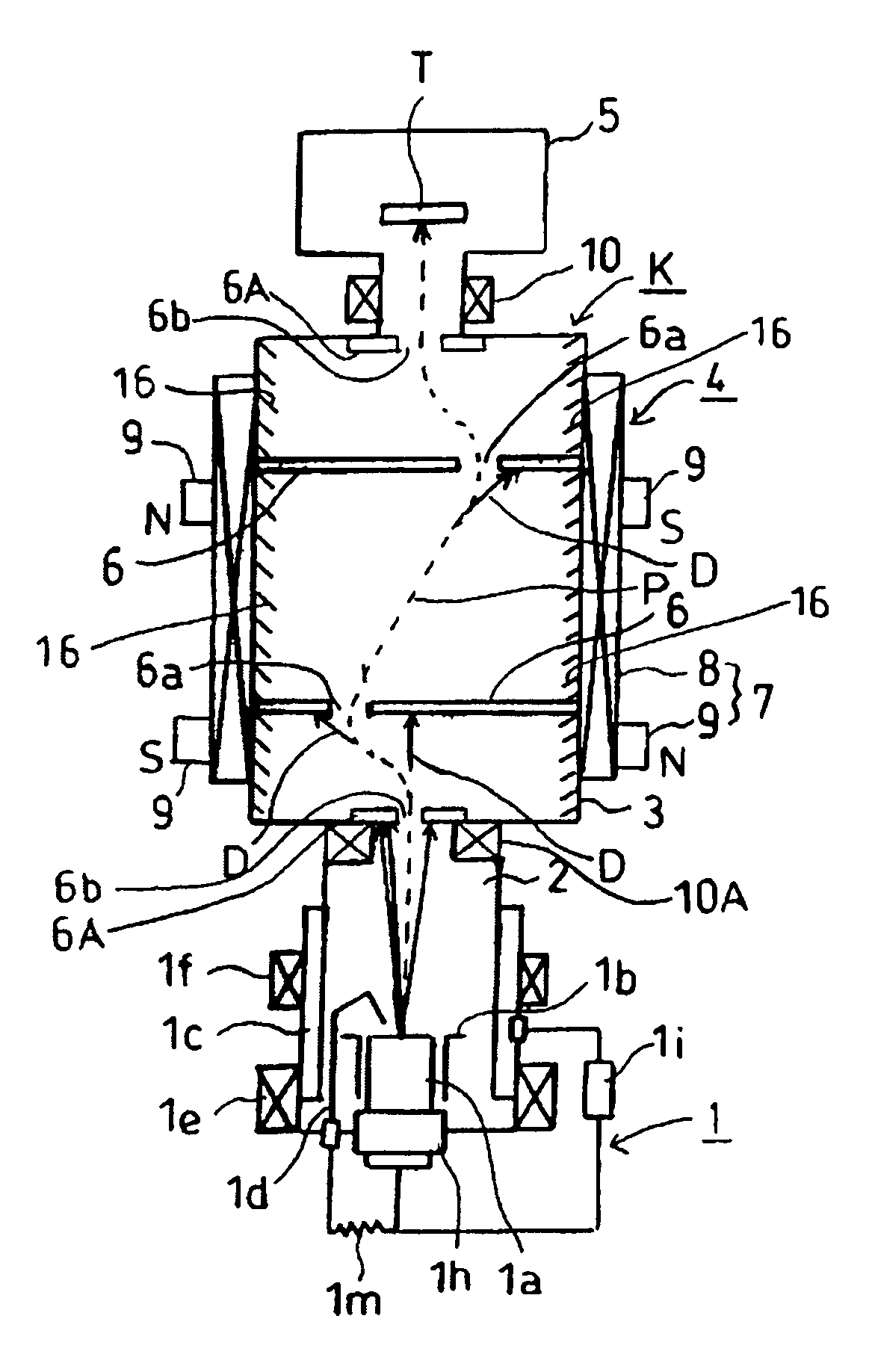
[0090]As follows, the preferred embodiments of the droplet removing device in plasma generator concerning the present invention are explained in details based on FIG. 1 to FIG. 11. FIG. 1 is a sectional schematic diagram of the plasma generator including the droplet removing device concerning the present invention. When the plasma processing section is added to this apparatus, the plasma processing device is completed.

[0091]As shown in FIG. 1, the plasma generator including the droplet removing device of this first embodiment can be assembled as the plasma processing device by integrating with the plasma processing section 5 containing the article being processed T. In the plasma processing method using this plasma processing device, the plasma P is generated generally by performing the vacuum arc discharge under vacuum atmosphere, the plasma P is transported to the plasma processing section 5, and the article being processed T arranged in this plasma processing section 5 is receive...

fourth embodiment

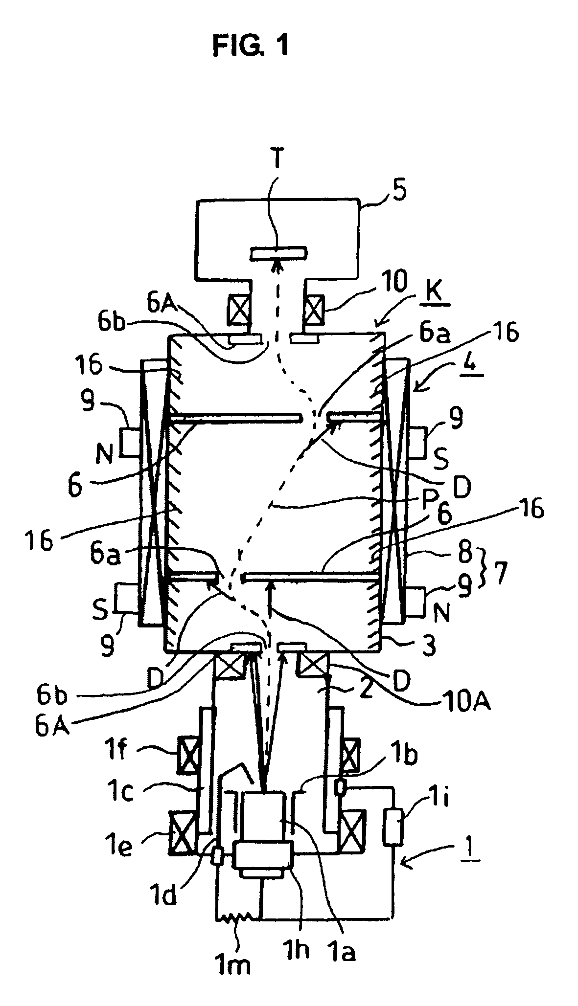
[0122]Therefore, big droplets D going straight from the main traveling passage 2 are removed by traveling into the droplet traveling passage 13, and small droplets D traveling with the plasma P advancing in the supplemental traveling passage 14 are removed by colliding with the wall surface of two apertures 6 in the tubular traveling passage 3. According to this fourth embodiment, since big droplets D are removed by going straight toward the droplet traveling passage 13, the plasma P arriving at the surface of the article being processed T in the plasma processing section 5 becomes to have the very high purity after passing through the tubular traveling passage 3. Therefore, the surface of the article being processed T can be treated with very high accuracy.

[0123]FIG. 11 is the sectional schematic diagram showing the plasma generator including the droplet removing device of the fifth embodiment. Still, the same numerals are given to the same members or same portions in said first em...

fifth embodiment

[0124]Therefore, big droplets D going straight from the main traveling passage 2 are removed by traveling into the droplet traveling passage 13, and small droplets D traveling with the plasma P advancing in the supplemental traveling passage 14 are removed by colliding with the wall surface of two apertures 6 in the tubular traveling passage 3. According to this fifth embodiment, since big droplets D are removed by going straight toward the droplet traveling passage 13, the plasma P arriving at the surface of the article being processed T in the plasma processing section 5 becomes to have very high purity after passing through the tubular traveling passage 3. Therefore, the surface of the article being processed T can be treated with very high accuracy.

[0125]It is needless to say that the present invention is not limited to the above-described embodiments and modifications; various modifications and design changes, etc. are included in the scope of the present invention within the l...


PUM

PropertyMeasurementUnit
sizeaaaaaaaaaa
sizeaaaaaaaaaa
thicknessaaaaaaaaaa

Abstract

A device for removing droplets in a plasma generator including a tubular traveling passage through which plasma and droplets travel under mixed state is formed, an aperture having a passing hole at an eccentric position is provided in the tubular traveling passage, and a magnetic field generator passing the plasma through the eccentric passing hole of the aperture arranged on an outer circumference of the tubular traveling passage. The plasma further passes through the eccentric passing hole of the aperture after being bent in the tubular traveling passage by a magnetic field generated from the magnetic field generator and the droplets are removed by colliding against the wall face of the aperture at the time of bending.

Description

FIELD OF THE INVENTION[0001]The present invention relates to a droplet removing device in plasma generator by which a plasma is generated by a vacuum arc discharge performed in an arc discharge section set under a vacuum atmosphere and cathode material particles (referred to as droplets) produced subsidiarily from the cathode at a time of plasma generation are removed.BACKGROUND ART[0002]In general, it is known that thin film is formed on the surface of solid material in plasma and a solid surface characteristic is improved by injecting an ion. Film formed by using of a plasma including metal ion and metalloid ion can strengthen the characteristics of abrasion resistance and corrosion resistance of a solid surface, so that it is useful as protective film, optics thin film and transparent conductivity film. As an approach to generate the metal ion and the metalloid ion, there is a vacuum arc plasma method. A vacuum arc plasma is formed by an arc discharge generated between cathode an...

Claims


Application Information

Patent Timeline
Patent Type & Authority Patents(United States)
IPC IPC(8): B03C1/32
CPCC23C14/325H01J37/32633H01J2237/022
Inventor SHIINA, YUICHI
Owner FERROTEC
Why Eureka
Try Eureka