Film forming method, method for manufacturing organic electroluminescent device, organic electroluminescent device, and electronic apparatus

a technology of electroluminescent devices and film forming methods, which is applied in the direction of manufacturing tools, natural mineral layered products, instruments, etc., can solve the problems of reducing the throughput of solvents with a single component, reducing the time to perform drying, and reducing so as to reduce the flow rate of solvents and reduce the evaporation rate of the entire solven

Active Publication Date: 2011-08-02
KATEEVA
View PDF10 Cites 17 Cited by
  • Summary
  • Abstract
  • Description
  • Claims
  • Application Information

AI Technical Summary

Benefits of technology

[0009]An advantage of the present invention is to provide a film forming method capable of obtaining a flat film, a method for manufacturing an organic electroluminescent device, an organic electroluminescent device and an electronic apparatus.
[0010]One aspect of the invention is a film forming method for forming a film including arranging a liquid composition on a substrate and drying the liquid composition, the liquid composition being obtained by dissolving a functional material in a solvent with a plurality of species of liquid mixed therein. The method includes: a first depressurizing process in which a pressure surrounding the liquid composition arranged on the substrate is reduced at a first depressurizing speed; a pressurizing process in which the pressure surrounding the liquid composition is increased to a predetermined pressure, after the first depressurizing process; and a second depressurizing process in which the pressure surrounding the liquid composition is reduced at a second depressurizing speed, after the pressurizing process.
[0011]In this case, the evaporation rate of the entire solvent is decreased by increasing the pressure surrounding the liquid composition to the predetermined pressure in the pressurizing process. In other words, not only the evaporation amount (JE) of the solvent of the central part in the liquid composition but also the evaporation amount (JC) of the solvent of the peripheral part in the liquid composition is decreased. Accordingly, the difference between JE and JC becomes smaller, thereby reducing also the flow rate of the solvent moving from the central part towards the peripheral part in the liquid composition. As the flow rate of the solvent is thus reduced, the solute diffuses in the liquid composition. Therefore, the concentration of the solute is constant in the central part and the peripheral part of the liquid composition. The second depressurizing process is performed with the concentration of the solute being constant, thereby making it possible to obtain a flat film. It should be noted that “the predetermined pressure” means the pressure capable of reducing the evaporation speed of the entire solvent and is preferably an atmosphere pressure, for example.
[0012]Further, it is preferable that the pressurizing process further include supplying inert gas around the liquid composition.
[0013]In this case, it is possible to prevent the liquid composition from deteriorating since inert gas is supplied around the liquid composition. It should be noted that as inert gas nitrogen gas or argon gas, for example, is preferably used.
[0014]Furthermore, it is preferable that the pressurizing process further include supplying vapor of the solvent around the liquid composition.

Problems solved by technology

It is very difficult for solvent with a single component to fulfill those two functions.
As a result, the solute stacks in the peripheral part, so there arises a problem in that after evaporation of the solute, only such a film (for example, the hole injection layer) 132 can be obtained that the central part is thinner and the peripheral part is thicker, as shown in FIG. 16.
On the other hand, when the drying speed is reduced, it takes much time to perform drying, which disadvantageously reduces the throughput.

Method used


Image

  • Film forming method, method for manufacturing organic electroluminescent device, organic electroluminescent device, and electronic apparatus
  • Film forming method, method for manufacturing organic electroluminescent device, organic electroluminescent device, and electronic apparatus
  • Film forming method, method for manufacturing organic electroluminescent device, organic electroluminescent device, and electronic apparatus

Examples


first embodiment

[0039]Hereinafter, a first embodiment of the invention will be described with reference to the drawings.

[0040]Organic EL Device

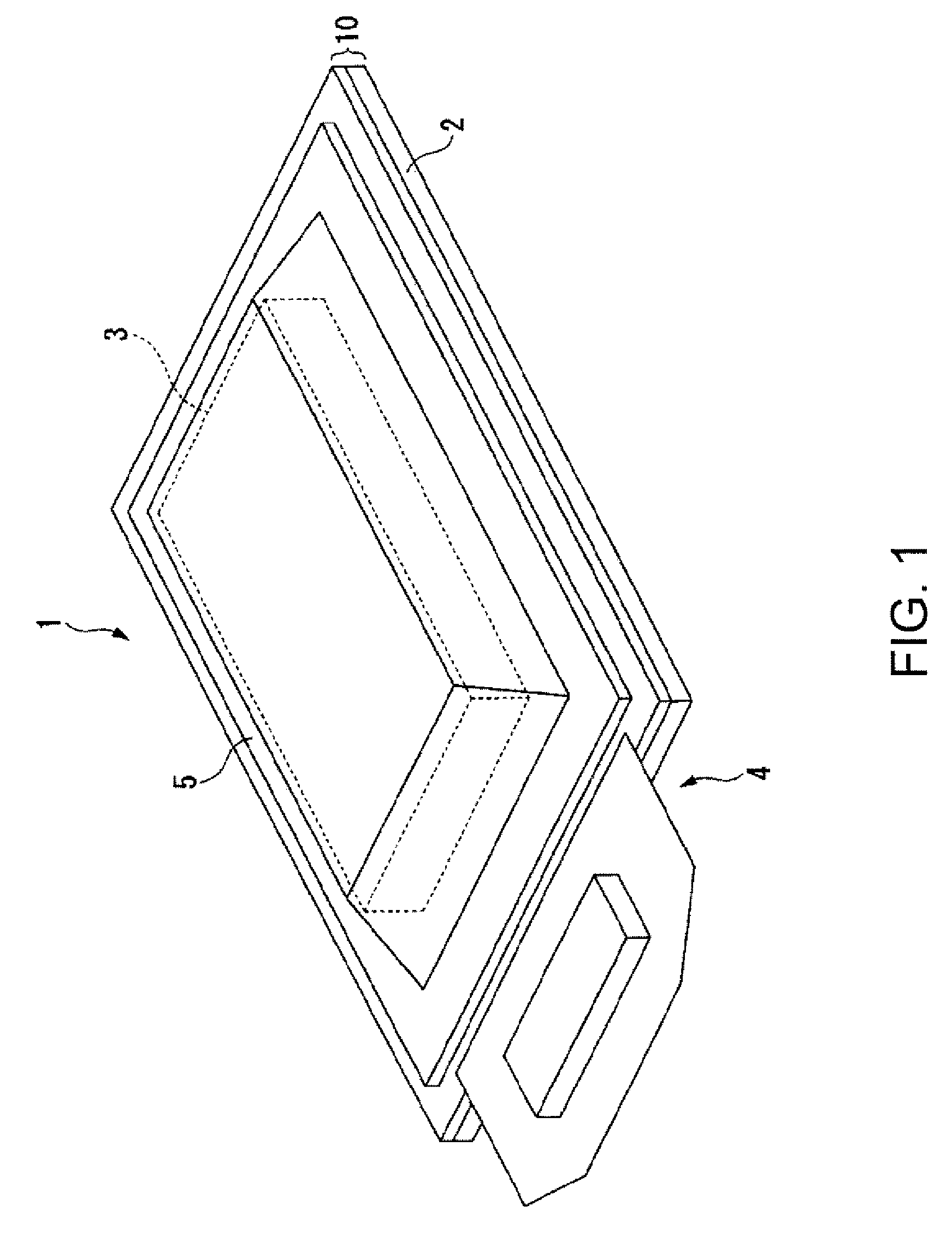
[0041]FIG. 1 is a perspective view schematically showing the entire construction of an organic EL device 1. In the following figures, the scale is changed as appropriate so that each part is large enough to be recognized.

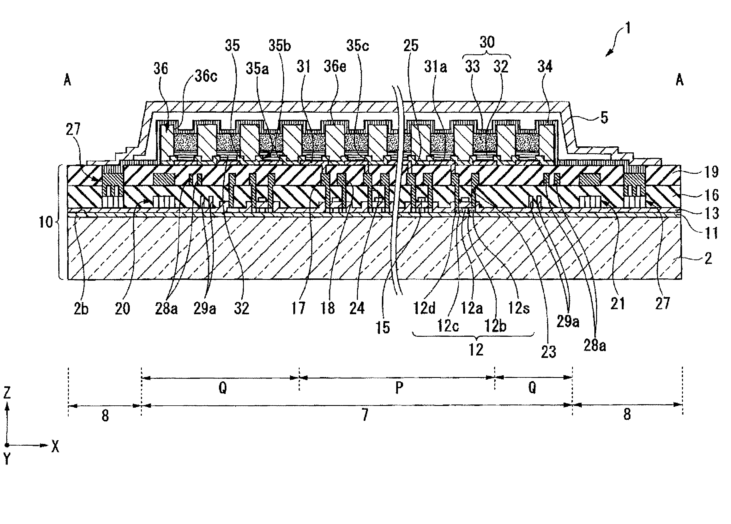
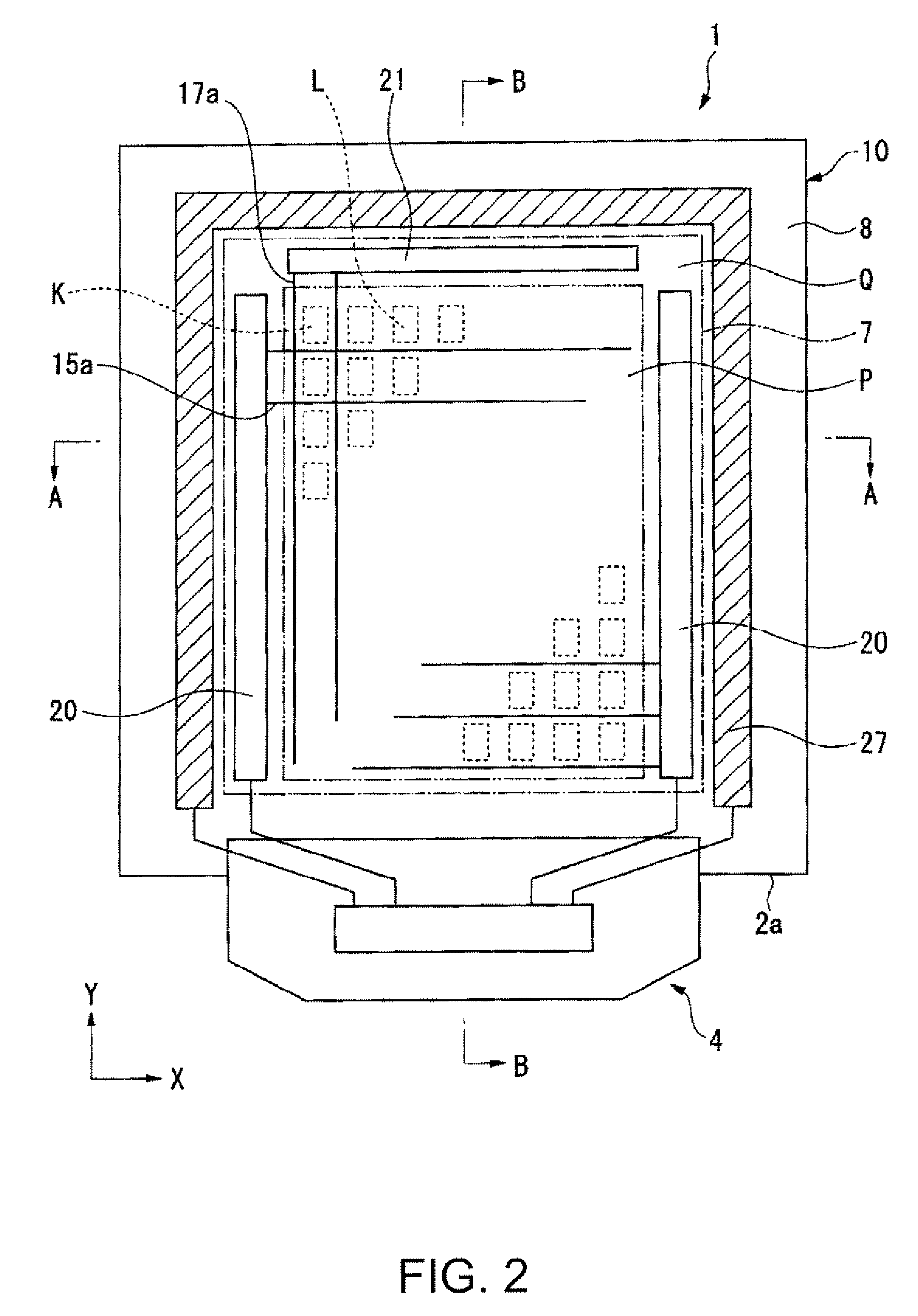
[0042]The organic EL device 1 has a base 10 composed of a substrate 2 with wires, insulating layers or the like being formed thereon, an organic EL element part 3 formed on the base 10, a driving part 4 attached to an end 2a of the base 10, and a sealing member 5 that covers the organic EL element part 3 and the base 10. The organic EL element part 3 emits light depending on signals supplied from the driving part 4, thereby making it possible to display images, moving images or the like. As to this embodiment, there is described as an example the organic EL device 1 of the active matrix type with a Thin Film Transistor (TFT) formed therein a...

second embodiment

[0095]Next, a second embodiment of the invention will be described. As in the case of the first embodiment, in the following, the scale of the figures to which reference is made is changed as appropriate so that each part is large enough to be recognized. Further, the same reference symbols are provided to the same components as those of the first embodiment of the invention and the description thereof will be omitted. It should be noted that the entire construction of the organic EL device according to this embodiment is substantially the same as the entire construction of the organic EL device 1 according to the first embodiment of the invention. Therefore, the description thereof will be omitted.

[0096]According to the first embodiment of the invention, inert gas (nitrogen gas or argon gas) is used as gas supplied around the ink 50 (60) in the pressurizing step. According to this embodiment, the vapor of the mixed solvent contained in the ink 50 (60) is supplied around the ink 50 ...


PUM

PropertyMeasurementUnit
pressureaaaaaaaaaa
temperatureaaaaaaaaaa
pressureaaaaaaaaaa

Abstract

A film forming method for forming a film including arranging a liquid composition on a substrate and drying the liquid composition, the liquid composition being obtained by dissolving a functional material in a solvent with a plurality of species of liquid mixed therein, is provided. The method includes:a) firstly reducing a pressure surrounding the liquid composition arranged on the substrate at a first depressurizing speed;b) increasing the pressure surrounding the liquid composition to a predetermined pressures after the step a); andc) secondly reducing the pressure surrounding the liquid composition at a second depressurizing speed, after the step b).

Description

BACKGROUND OF THE INVENTION[0001]1. Technical Field[0002]The present invention relates to a film forming method, a method for manufacturing an organic electroluminescent device, an organic electroluminescent device, and an electronic apparatus.[0003]2. Related Art[0004]When forming a film such as a light-emitting layer of, for example, an organic electroluminescent device (hereinafter also referred to as an organic EL device), there is used a technique in which on a substrate ink, that is obtained by dissolving in a solvent composed of a plurality of species of liquid mixed with each other a functional material that forms a light-emitting layer, is applied and then dried, thereby forming a film.[0005]There are mainly two functions which are demanded of the ink. One function is capability to be applied on the substrate, and the other is ability to form a flat film. It is very difficult for solvent with a single component to fulfill those two functions. Therefore, there is often used,...

Claims


Application Information

Patent Timeline
Patent Type & Authority Patents(United States)
IPC IPC(8): B05D5/00
CPCH01L51/0003H01L51/0007G02F1/133516H01L27/3244H01L27/3295H01L51/56H10K59/122H10K59/12H10K71/15H10K71/12H10K71/00H05B33/10
Inventor SAKAI, HIROFUMITANAKA, TAKAYA
Owner KATEEVA
Why Eureka
Try Eureka