
Carbon dioxide emission reduction method

a carbon dioxide and emission reduction technology, applied in the field of carbon dioxide emission reduction methods, can solve the problems of adding to the carbon dioxide emissions of the facility, adding to the formation of additional carbon dioxide, etc., and achieve the effect of increasing the production of carbon dioxid

Inactive Publication Date: 2011-08-30
PRAXAIR TECH INC
View PDF13 Cites 17 Cited by
  • Summary
  • Abstract
  • Description
  • Claims
  • Application Information

AI Technical Summary

Benefits of technology

The present invention provides a method for reducing carbon dioxide emissions in a refinery. The method involves using a catalyst to react hydrogen with hydrocarbons and sulfur compounds present in the refinery off gas stream. The resulting stream is then combined with a steam stream to produce a reactant stream. The reactant stream is then cooled and hydrogen sulfide is adsorbed from the stream. The resulting stream is then combined with a fuel gas stream to produce a reformed stream. The carbon monoxide and steam in the reformed stream are then reacted in a water-gas shift reactor to produce a hydrogen and carbon dioxide containing gas stream. The carbon dioxide is then separated from the gas stream and utilized as fuel. The method reduces carbon dioxide emissions from the refinery and ensures a more efficient use of fuel.

Problems solved by technology

This results in additional carbon dioxide being formed.
All of this combustion adds to the carbon dioxide emissions of the facility.
However, such streams often have a high olefin content that will deactivate the catalyst within the steam methane reformer.

Method used


Image

  • Carbon dioxide emission reduction method
  • Carbon dioxide emission reduction method
  • Carbon dioxide emission reduction method

Examples


Embodiment Construction

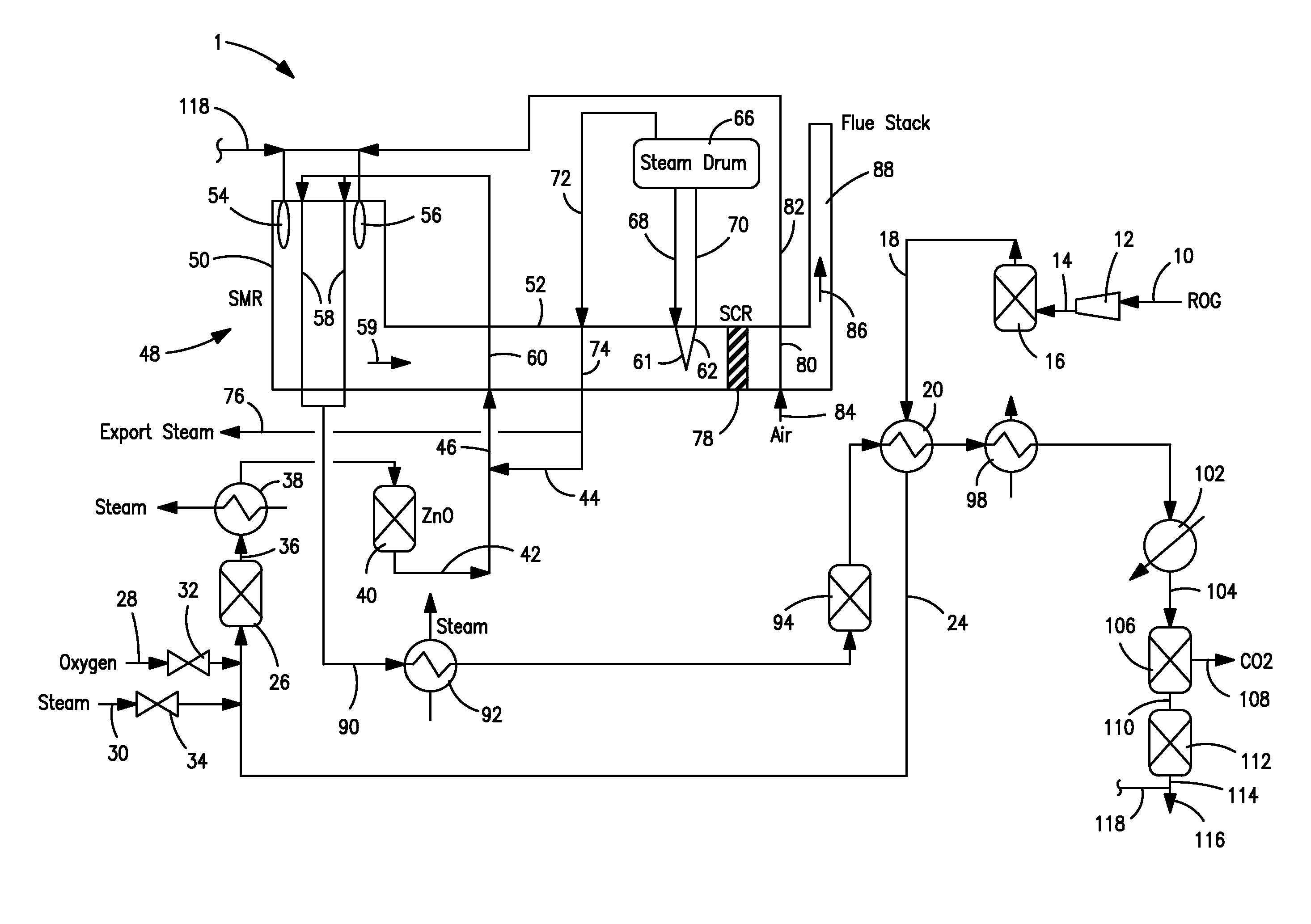
[0022]With reference to FIG. 1, a steam methane reforming installation 1 is illustrated in which a hydrocarbon containing stream to be reformed by steam methane reforming originates as in incoming refinery off gas stream 10 that is obtained upstream from a refinery fuel gas header and down stream from a sulfur removal unit that is typically an amine system known in the art. It is understood, however, that this is for purposes of illustration only and in fact, natural gas could be mixed with the refinery off gas stream 10 and then same could be processed as described hereinbelow.

[0023]Refinery off gas stream 10 could be a fluidic catalytic cracker off gas, a sweet refinery gas, a coker off gas or other type of off gas containing high amounts of hydrocarbons with two or more carbon atoms. Typically, a refinery off gas stream will contain no less than about 50% by volume on a dry basis of hydrocarbons and / or at least 3% by volume of olefins. Typical compositions of such streams are, ho...


PUM

PropertyMeasurementUnit
lengthaaaaaaaaaa
pressureaaaaaaaaaa
discharge pressureaaaaaaaaaa

Abstract

Carbon dioxide emissions within a refinery are reduced by reforming a hydrocarbon containing feed at low pressure to enhance the conversion of methane to hydrogen and carbon monoxide and thereby reduce methane slip. The hydrocarbon containing feed is composed entirely or at least in part of a refinery off gas. The resulting reformed stream is then subjected to water-gas shift conversion to form a shifted stream from which carbon dioxide is separated. As a result of the separation and the low pressure reforming, hydrogen containing fuel gas streams, that are thereby necessary lean in carbon dioxide and methane, are used in firing the steam methane reformer and other fuel uses within the refinery to reduce carbon dioxide emissions. The carbon dioxide that is separated can be sequestered or used in other processes such as enhanced oil recovery.

Description

FIELD OF THE INVENTION[0001]The present invention relates to a method of reducing carbon dioxide emissions within a refinery in which fuel gas streams are produced by reforming a hydrocarbon containing stream, composed all or in part of a refinery off gas, at low pressure to reduce methane slip and separating carbon dioxide from a reformed stream subjected to one or more water-gas shift reactors. More particularly, the present invention relates to such a method in which one of the fuel streams is used in firing the reformer and the other of the fuel streams is returned to the refinery fuel header.BACKGROUND OF THE INVENTION[0002]Steam methane reforming of a hydrocarbon containing feed is practiced to produce hydrogen for such refinery uses as hydrotreating and hydrocracking. As a result, steam methane reformers are operated in connection with fuel refining facilities. A variety of off gas streams are produced in refineries from processes such as fluidic catalytic cracking, coking, c...

Claims


Application Information

Patent Timeline
Patent Type & Authority Patents(United States)
IPC IPC(8): C01B3/26
CPCC01B3/384C10K3/04C01B3/48Y02C10/04C01B2203/0233C01B2203/0283C01B2203/0415C01B2203/0475C01B2203/0495C01B2203/0822C01B2203/0894C01B2203/1258C01B2203/142C01B2203/148C01B2203/86Y02C20/40Y02P20/10Y02P30/00B01D53/62C01B3/38C01B3/382F25J3/02
Inventor DRNEVICH, RAYMOND FRANCISSHAH, MINISH MAHENDRAPAPAVASSILIOU, VASILIS
Owner PRAXAIR TECH INC
Learn More