Charged-particle condensing device

a condensing device and charged particle technology, applied in the field of mass spectrometers, can solve the problems of reducing the utilization efficiency of formed ions, and reducing the speed of v

Inactive Publication Date: 2011-09-06
SHIMADZU CORP
View PDF12 Cites 6 Cited by
  • Summary
  • Abstract
  • Description
  • Claims
  • Application Information

AI Technical Summary

Benefits of technology

[0021]According to the present invention the ions generated in an ionization chamber are guided by electric RF- and DC-fields together with other charged particles towards an orifice through which they must pass to enter the mass spectrometer or the mobility spectrometer. This includes many ions which otherwise would have been lost because they would have impinged on surfaces. Consequently the utilization efficiency of the formed ions is increased significantly and the ion intensity in the finally recorded mobility spectrum or mass spectrum is improved and thus is the sensitivity of the performed measurement.
[0022]In the embodiment in which RF- and DC-potentials of proper magnitude have been applied to a plurality of substantially circular and substantially concentric electrodes one finds that ions together with other charged particles are trapped in a broad region above the electrode array and guided towards said orifice placed in the center of the electrode array.
[0023]In the embodiment in which RF- and DC-potentials of proper magnitude have been applied to a plurality of substantially parallel electrodes one finds also that ions together with other charged particles are trapped in a broad region above the electrode array. However, this electrode array will guide them only in a direction perpendicular to the orientation of said electrodes. Passing them through an elongated orifice and accelerating them towards a second such array of substantially parallel electrodes that are oriented orthogonally to the first array the ions are condensed to a narrow cloud that efficiently can be extracted through said orifice.
[0024]When ions reach the trapping region above said substantially circular or substantially parallel electrode arrangements, the velocity “v” of these ions or other charged particles can be so high that the effective repelling force “F” caused by the RF-fields is too small to trap them. Using intermediate grids and diaphragms and applying to them retarding potentials their velocity “v” can be reduced sufficiently.
[0025]The trapping efficiency of the RF-fields increases with the mass of the ions under consideration and the magnitude of the RF-fields. Thus it can be of advantage to choose the magnitude of the RF-fields such that ions or other charged particles of interest are well trapped while lighter ones of no interest are not trapped and thus impinge on the electrode array. At least some of the undesired particles thus are not transmitted into the mass spectrometer or the mobility spectrometer and consequently improve the selectivity of the ion analysis.

Problems solved by technology

To guide ions through one or through several small orifices is always difficult to achieve so that commonly a large percentage of the formed ions will impinge on the sides of said orifice and be lost for the analysis
In both methods often the nozzle and / or the carrier gas is heated so as to enhance the evaporation rate of the droplets since still intact droplets would be detrimental to the functioning of the mobility spectrometer or the mass spectrometer.
However, in most cases only a portion of the formed ions enter the capillary and even of these many will interact with the walls of the capillary and thus be lost.
In both methods, however, only a portion of the formed ions can be utilized.

Method used


Image

  • Charged-particle condensing device
  • Charged-particle condensing device
  • Charged-particle condensing device

Examples


Embodiment Construction

[0075]The present invention aims to improve the coupling efficiency of an atmospheric pressure ion source to a mass spectrometer or to a mobility spectrometer by providing electric fields that act as a condensing device for charged particles before they are fed to the spectrometer. A complete such system is illustrated with all its essential parts in FIGS. 8 and 9.

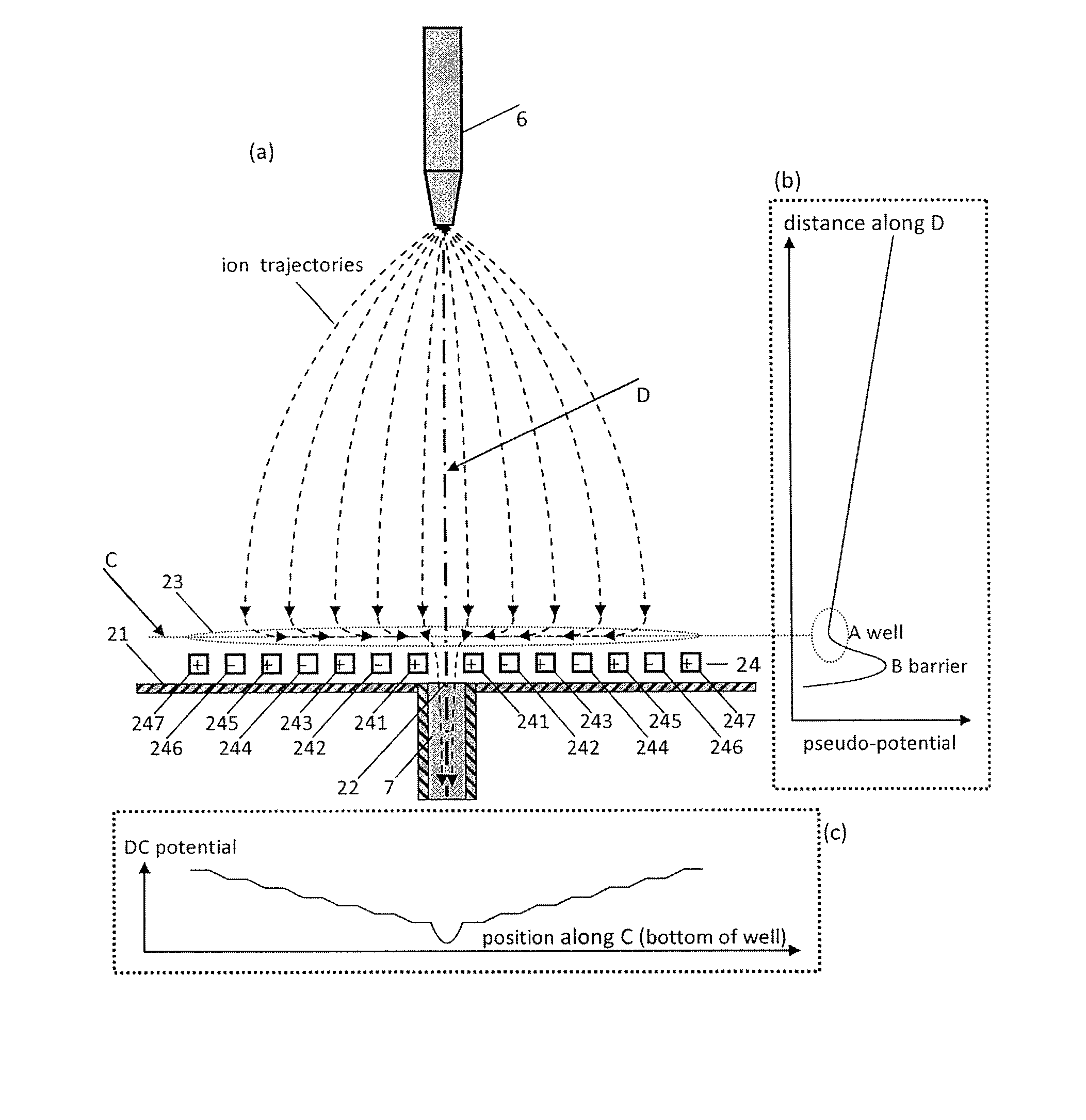
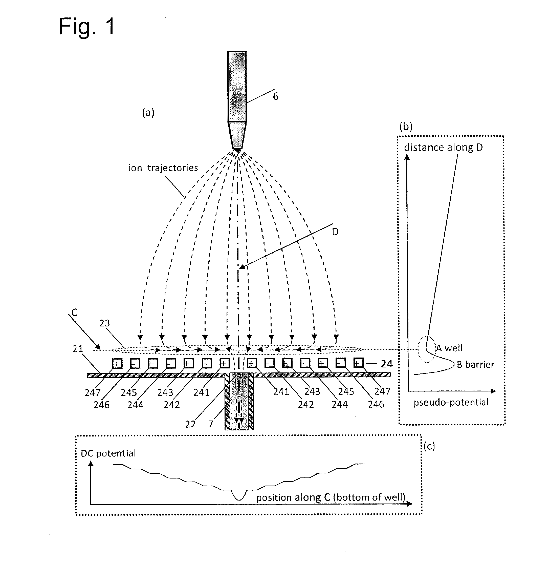
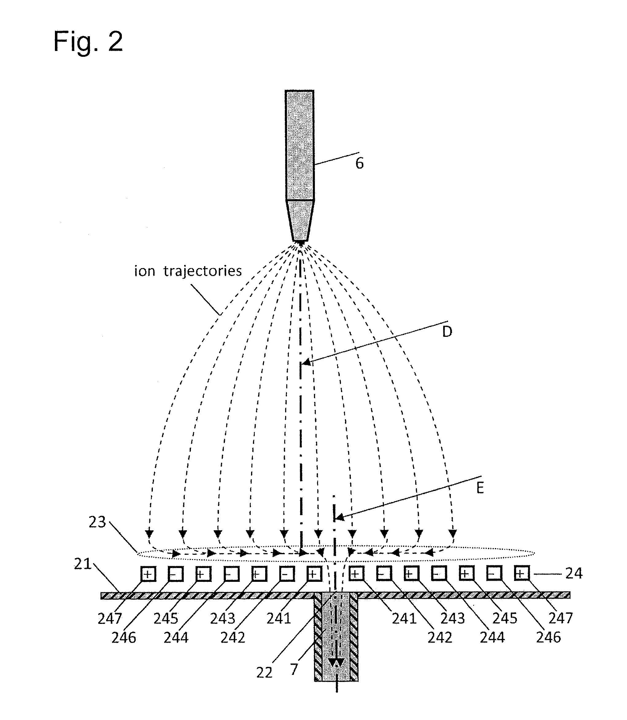
[0076]A mass spectrometer that is equipped with an atmospheric pressure ion source is illustrated in FIG. 8. There is an ionization chamber (1) that features a nozzle (6) into which molecules of interest are introduced dissolved in a liquid sample or in the effluent of a liquid chromatograph, not shown. From this nozzle charged droplets emerge from which ionized molecules evaporate as well as neutral molecules that either stay uninvestigated or must be ionized by electric discharges or laser interaction. This evaporation of droplets is enhanced when the droplets pass into the usually heated so-called desolvation pipe (7). ...


PUM


Abstract

Ions and charged droplets move from the nozzle (6) towards the orifice (22) of a charged-particle transport device or the desolvation pipe (7). This particle motion is governed by the distribution of the pseudo-potential along particle trajectories. There are RF-voltages applied to neighboring electrodes (241-246) of the electrode array (24) cause the charged particles to substantially hover above the electrode array (24). Right before the ions come to the electrode array (24) they thus experience a repelling force “F” perpendicular to the surface of the electrode array (24). This force “F” causes an effective barrier (B) right before the electrode array (24) and consequently a pseudo-potential well (A) where the charged particles stop their motion parallel to the plume axis (D). Thus they accumulate around the center line (C) of this well (A). Applying additionally to the RF-potentials also DC-potentials to neighboring electrodes within the electrode array (24) small DC-fields can be formed within the well area (23). These additional DC-fields drive the charged particles towards the axis of symmetry (C) and thus towards the orifice (22) of a charged-particle transport device or the desolvation pipe (7). Thus, many of the charged particles which would normally impinge on the wall (21) around the orifice (22) can now be analyzed.

Description

TECHNICAL FIELD[0001]The present invention relates to a mass spectrometer, and more specifically to the ion source of such a spectrometer that forms a cloud of ions or other charged particles which must be extracted through a small orifice into a mass spectrometer or mobility spectrometer with the ions or other charged particles being formed in a gas of approximately one or a few atmospheres, as is done in an electrospray ion source (ESI), an atmospheric pressure chemical ion source (APCI), a high-frequency inductively coupled plasma ion source (ICP), or alternatively in a gas of reduced pressure as is done in an electron impact ion source (EI), a chemical ion source (CI), a laser ion source (LI) or a plasma ion source (PI).BACKGROUND ART[0002]To ionize molecules or atoms for the analysis in a mass spectrometer or a mobility spectrometer different ionization techniques are employed. Many of these techniques provide ions within a cloud from which only those can be investigated that e...

Claims


Application Information

Patent Timeline
Patent Type & Authority Patents(United States)
IPC IPC(8): H01J49/04H01J49/06
CPCH01J49/067
Inventor WOLLNIK, HERMANNUENO, YOSHIHIRO
Owner SHIMADZU CORP
Why Eureka
Try Eureka