
Protective layer for protecting a component against corrosion and oxidation at high temperatures, and component

a technology of protective layer and component, applied in the direction of wind motor components, non-positive displacement fluid engines, liquid fuel engine components, etc., can solve the problems of mechanical failure, deterioration of the ductility of the protective layer, and no protective layer described is qualified for special conditions, so as to increase the protection against corrosion and oxidation

Inactive Publication Date: 2011-09-27
SIEMENS ENERGY GLOBAL GMBH & CO KG
View PDF34 Cites 10 Cited by
  • Summary
  • Abstract
  • Description
  • Claims
  • Application Information

AI Technical Summary

Benefits of technology

The invention provides a protective layer that is stable at high temperatures and can withstand corrosion and oxidation. The layer is particularly well-suited for use in gas turbines and steam turbines. The layer is formed by a process that involves applying a coating to a base material and then subjecting it to a heat treatment. The protective layer has a unique structure that includes brittle chromium-rhenium precipitates and a transition region between the layer and the base material. These factors contribute to the layer's susceptibility to cracking and detachment in operation. The invention also provides a component with the protective layer for increased protection against corrosion and oxidation.

Problems solved by technology

However, in view of the lack of more specific further ranges for possible admixtures, none of the protective layers described is qualified for special conditions, such as for example on rotor blades and guide vanes of gas turbines with high inlet temperatures which have to be operated for prolonged periods of time.
This typically gives rise to the problem that an increase in the levels of elements such as aluminum and chromium, which can increase the resistance of a protective layer to oxidation and corrosion, leads to a deterioration in the ductility of the protective layer, which means that mechanical failure, in particular the formation of cracks, is likely under mechanical loading which usually occurs in a gas turbine.

Method used


Image

  • Protective layer for protecting a component against corrosion and oxidation at high temperatures, and component
  • Protective layer for protecting a component against corrosion and oxidation at high temperatures, and component
  • Protective layer for protecting a component against corrosion and oxidation at high temperatures, and component

Examples


Embodiment Construction

ponent as claimed in the claims, which is in particular a component of a gas turbine or steam turbine, and which has a protective layer of the type described above to protect against corrosion and oxidation at high temperatures.

BRIEF DESCRIPTION OF THE DRAWINGS

[0024]The invention is explained in more detail below. In the drawing:

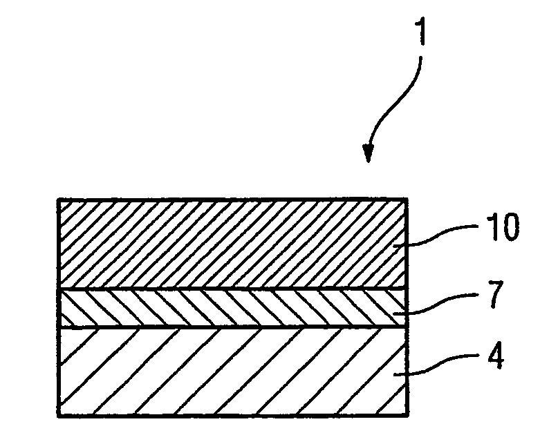
[0025]FIG. 1 shows a layer system having a protective layer,

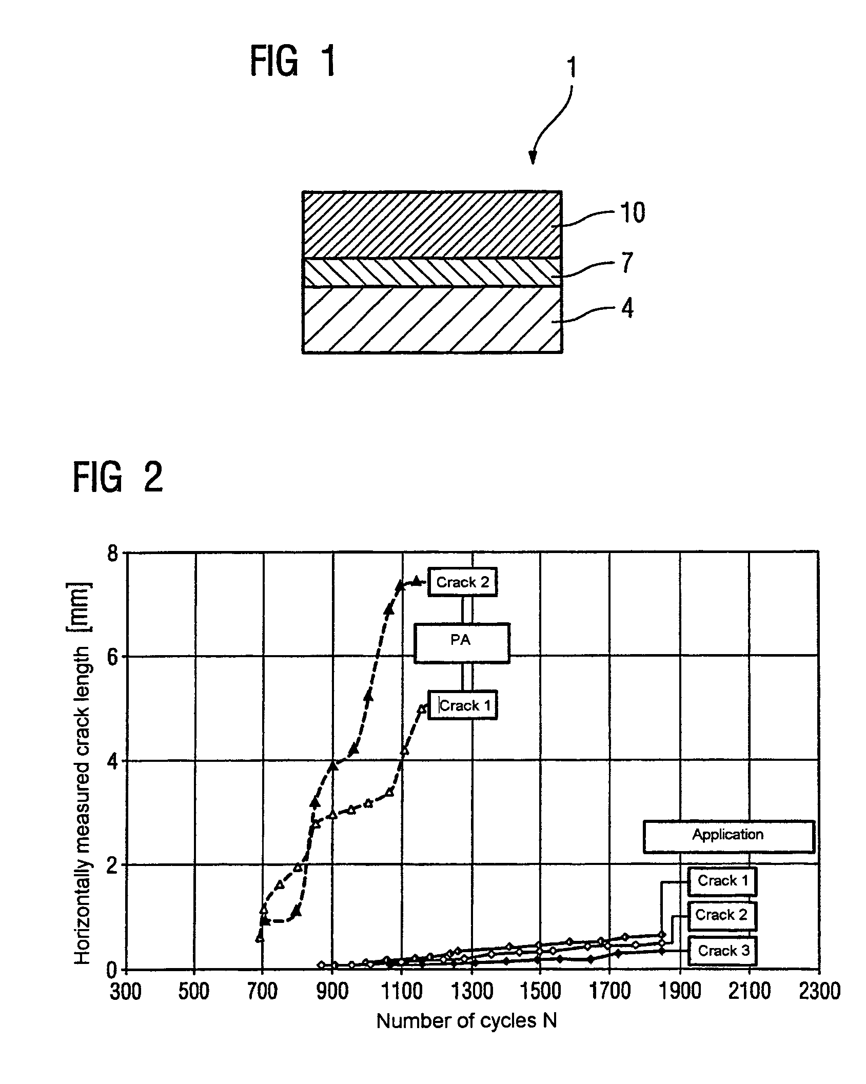
[0026]FIG. 2 shows test results of cyclical load tests,

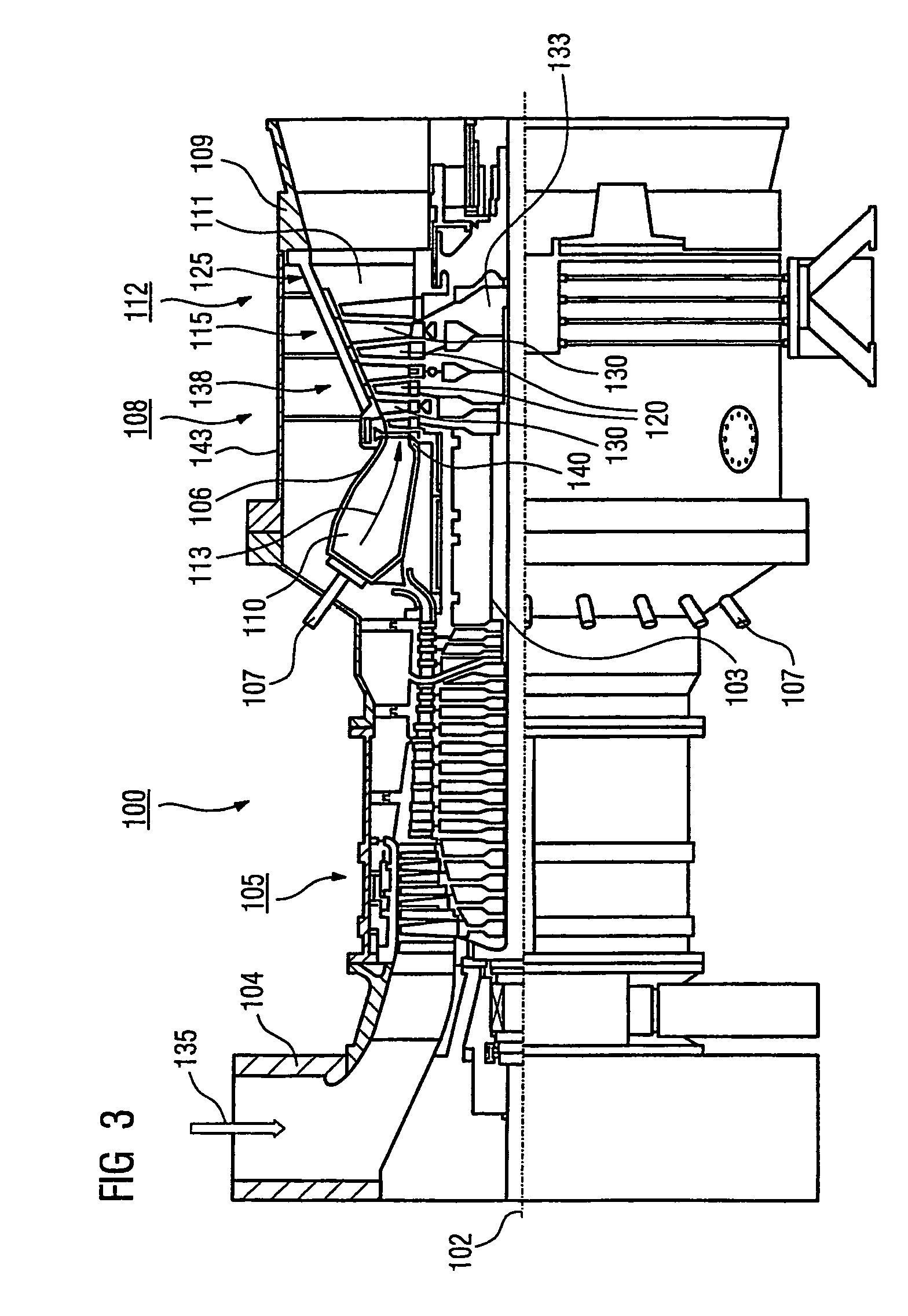
[0027]FIG. 3 shows a gas turbine,

[0028]FIG. 4 shows a combustion chamber, and

[0029]FIG. 5 shows a turbine blade or vane.

DETAILED DESCRIPTION OF THE INVENTION

[0030]According to the invention, a protective layer 7 (FIG. 1) for protecting a component against corrosion and oxidation at high temperature includes substantially the following elements (details of amounts in percent by weight):

[0031]0.5 to 2% rhenium,

[0032]15 to 21% chromium,

[0033]24 to 26% cobalt,

[0034]9 to 11.5% aluminum,

[0035]0.05 to 0.7% yttrium and / or at least one equivalent metal s...


PUM

PropertyMeasurementUnit
inlet temperaturesaaaaaaaaaa

Abstract

Known protective layers with a high Al and / or Cr content and additionally strengthened by Re form brittle phases which become more brittle during use under the influence of carbon. The protective layer according to the invention has the composition 0.5 to 2% rhenium, 24 to 26% cobalt, 15 to 21% chromium, 9 to 11.5% aluminum, 0.05 to 0.7% yttrium and / or at least one equivalent metal selected from the group consisting of scandium and the rare earth elements, 0 to 1% ruthenium, remainder cobalt and / or nickel and manufacturing-related impurities, and reveals scarcely any embrittlement caused by Cr / Re precipitates.

Description

CROSS REFERENCE TO RELATED APPLICATIONS[0001]This application is the US National Stage of International Application No. PCT / EP2004 / 010025, filed Sep. 8, 2004 and claims the benefit thereof. The International Application claims the benefits of European Patent application No. 03023644.2 filed Oct. 17, 2003. All of the applications are incorporated by reference herein in their entirety.FIELD OF THE INVENTION[0002]The invention relates to a protective layer for protecting a component against corrosion and oxidation at high temperatures as described in the claims, the component in particular being a component of a gas turbine, to a component as described in the claims and to a process as described in the claims.[0003]The invention relates in particular to a protective layer for a component which consists of a nickel-base or cobalt-base superalloy.BACKGROUND OF THE INVENTION[0004]Numerous protective layers for metallic components which are intended to increase the corrosion resistance and...

Claims


Application Information

Patent Timeline
Patent Type & Authority Patents(United States)
IPC IPC(8): B32B15/04A01N43/40C07D213/79C23C4/06C23C28/00C23C30/00F01D5/28
CPCB32B15/01C22C19/058C22C19/07C23C28/3215C23C28/3455C23C30/00F01D5/288C23C28/345C22C19/056Y10T428/12931Y02T50/67F05D2230/90F05D2300/121F05D2300/132F05D2300/15F05D2300/611Y10T428/12937Y10T428/12944Y02T50/60
Inventor STAMM, WERNER
Owner SIEMENS ENERGY GLOBAL GMBH & CO KG
Learn More