
Radiation probe and detecting tooth decay

Active Publication Date: 2011-09-27
TERAVIEW
View PDF20 Cites 96 Cited by
  • Summary
  • Abstract
  • Description
  • Claims
  • Application Information

AI Technical Summary

Benefits of technology

[0013]Although pulsed radiation is advantageous in that it allows the sample to be imaged with a plurality of frequencies, pulsed laser diodes are more expensive and also it is difficult to send a pulse of radiation down an optical fibre. Therefore, it is also desirable to use continuous wave (CW) radiation. Such CW radiation can be supplied by CW laser diodes. In a simple configuration, CW input radiation of two different frequencies is provided as input radiation to the probe, the CW frequencies are then used to generate THz radiation using an optically non-linear member configured to generate radiation with a frequency which is substantially the difference of that of the two input frequencies. Alternatively, the two CW input frequencies could be used to generate THz radiation using a photoconductive antenna or any of the other methods referred to in this specification.
[0091]The refractive index can also be used to probe differences in the refractive index associated with water. Indeed, images formed by panchromatic THz are very sensitive to water content. This is demonstrated by the strong and frequency-dependent n(ω) spectrum associated with water, which varies from approximately 1.3 to 3.3 over the THz / infrared frequency range. As such, the differences in water content between carious and non-carious regions (as discussed above in terms of an increase in porosity) will also allow the THz panchromatic n(ω) images to be used in the identification of carious regions in enamel simply by plotting the time of flight. In particular, increased porosity near or at carious regions should lead to different n(ω) in these regions, which should lead to a contrast mechanism between healthy and carious tissue in THz.

Problems solved by technology

It does not detect electro-magnetic radiation via a non direct method such as detecting a photo-current in the sample.

Method used


Image

  • Radiation probe and detecting tooth decay
  • Radiation probe and detecting tooth decay
  • Radiation probe and detecting tooth decay

Examples


Embodiment Construction

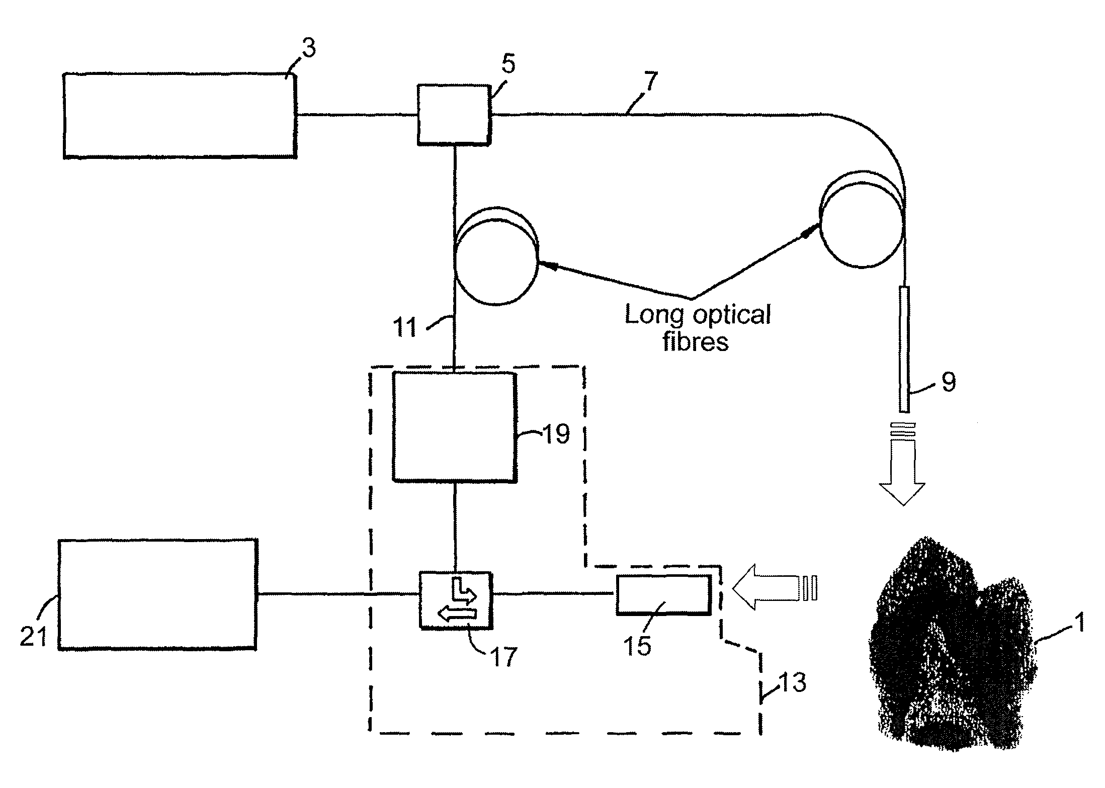
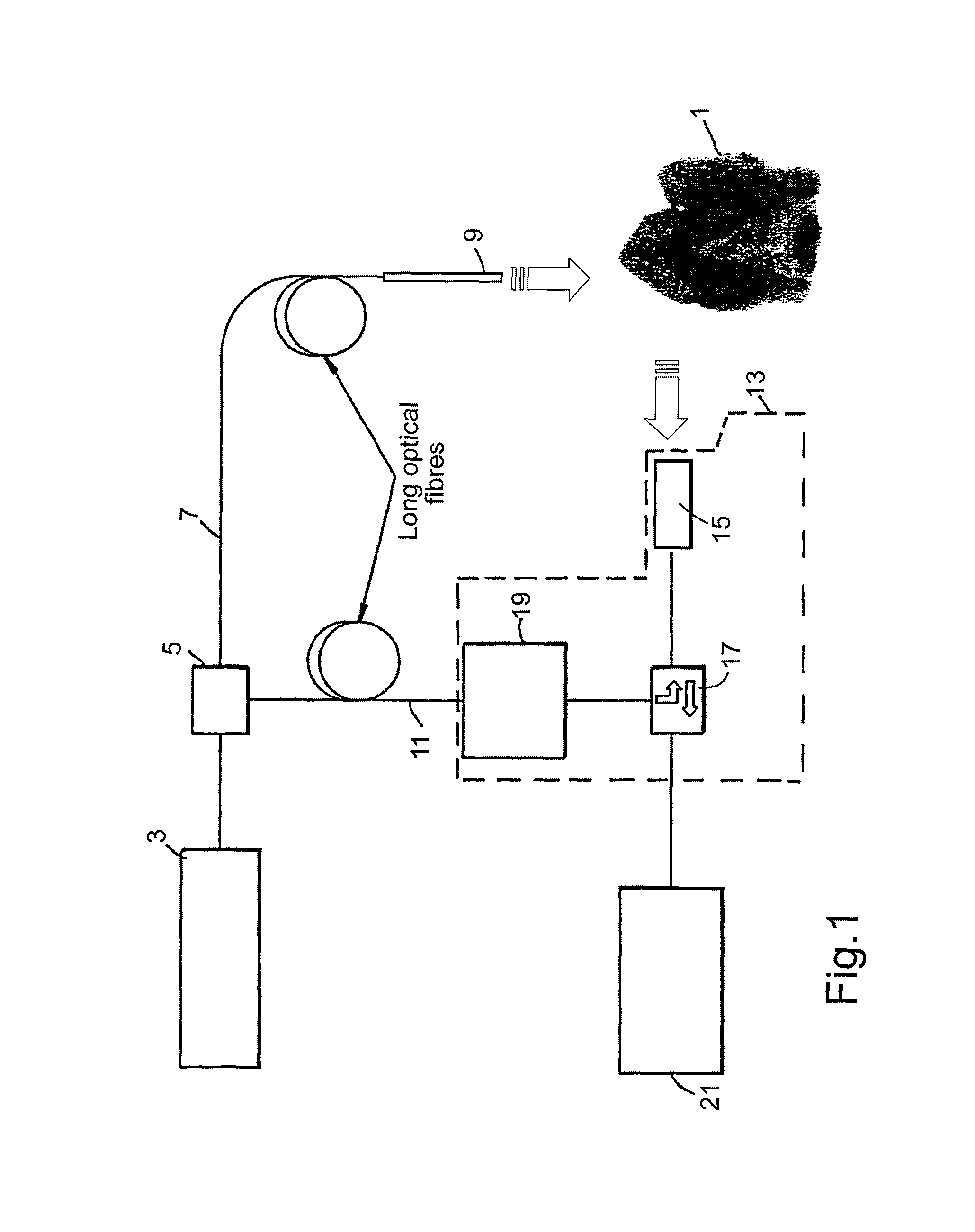
[0170]FIG. 1 shows a schematic outline of the functions of the THz probe. The object to be examined by the probe is tooth 1. An ultra fast laser source 3 provides pulsed radiation to a beam splitter 5. (Although, a continuous wave source could also be used as will be explained in relation to FIGS. 17 to 19). Beam splitter 5 then splits the beam to travel along two fibre optic cables 7, 11. Fibre optic cable 7 is connected to the THz emitter 9. Fibre Optic 11 is provided to the THz detection system 13. The THz detection system 13 has a THz detector 15 which detects radiation which is either passed through and / or been reflected from the tooth 1. The delay control may alternatively be placed in the fibre optic cable 7 leading to the THz emitter 9.

[0171]Information from the detected THz beam is then encoded onto the laser source beam from fibre optic cable 11. Fibre optic circulator 17 is in effect a radiation valve which is used to direct the beam from fibre 11 into the THz detector fo...


PUM


Abstract

A probe assembly for examining a sample, the assembly including a probe, a fiber optic cable for communicating signals to and / or from the probe, an emitter for emitting radiation to irradiate the sample and an electro-magnetic radiation detector for detecting radiation which is transmitted or reflected from the sample. The emitter includes a frequency conversion member which emits radiation in response to being irradiated with input radiation which has a different frequency to that of the emitted radiation. At least one of the emitter or detector is located in the probe. The probe is particularly for use as an endoscope or for imaging teeth. The invention also extends to a method of imaging teeth, and apparatus for imaging diseased teeth, for example, teeth with caries or suffering from periodontal disease.

Description

CROSS-REFERENCE TO RELATED APPLICATION[0001]This application is a continuation of application Ser. No. 10 / 031,784, filed Aug. 5, 2005, which is a 35 U.S.C. §§371 national phase conversion of PCT / GB00 / 02849, filed 24 Jul. 2000, which claims priority of Great Britain Application No. 9917407.0, filed 23 Jul. 1999. The PCT International Application was published in the English language.BACKGROUND OF THE INVENTION[0002]The present invention relates to probes which can be used to image or determine compositional information from structures using radiation with a frequency from 0.1 THz to 84 THz. The present invention also relates to a method for studying diseased teeth.[0003]Recently, there has been much interest in using THz radiation to look at a wide variety of samples using a range of methods. THz radiation can be used for both imaging samples and obtaining spectra at each pixel in an image. THz radiation penetrates most dry, non-metallic and non-polar objects like plastic, paper, tex...

Claims


Application Information

Patent Timeline
IPC IPC(8): A61B5/05A61C1/00G01N21/17A61B1/04A61B5/00A61B6/14A61B10/00A61C19/04G01N21/27G01N21/35G01N21/49G01N21/59
CPCA61B5/0088A61B5/417A61B6/145G01N21/3581G01N21/49G01N21/59A61B1/042A61B2562/0238A61B2562/085G01N21/3563G01N21/3577A61B6/512
Inventor ARNONE, DONALD DOMINICCIESLA, CRAIG MICHAEL
Owner TERAVIEW
Learn More