

Enhanced sensitivity vibrometer
a vibrometer and enhanced technology, applied in the field of laser vibrometers, can solve the problems of affecting the sensitivity of the diaphragm assembly in detecting the incoming pressure wave, affecting the sensitivity of the diaphragm assembly, so as to enhance the resolution of vibration and enhance the signal strength. , the effect of enhancing the signal strength
- Summary
- Abstract
- Description
- Claims
- Application Information
AI Technical Summary
Benefits of technology
Problems solved by technology
Method used
Image

Examples
example 1
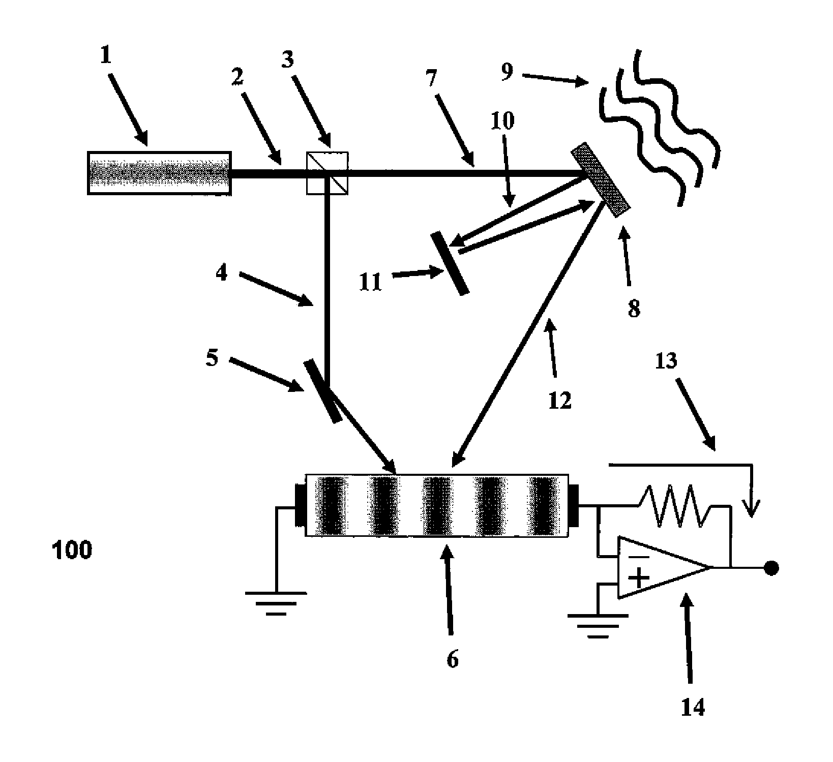
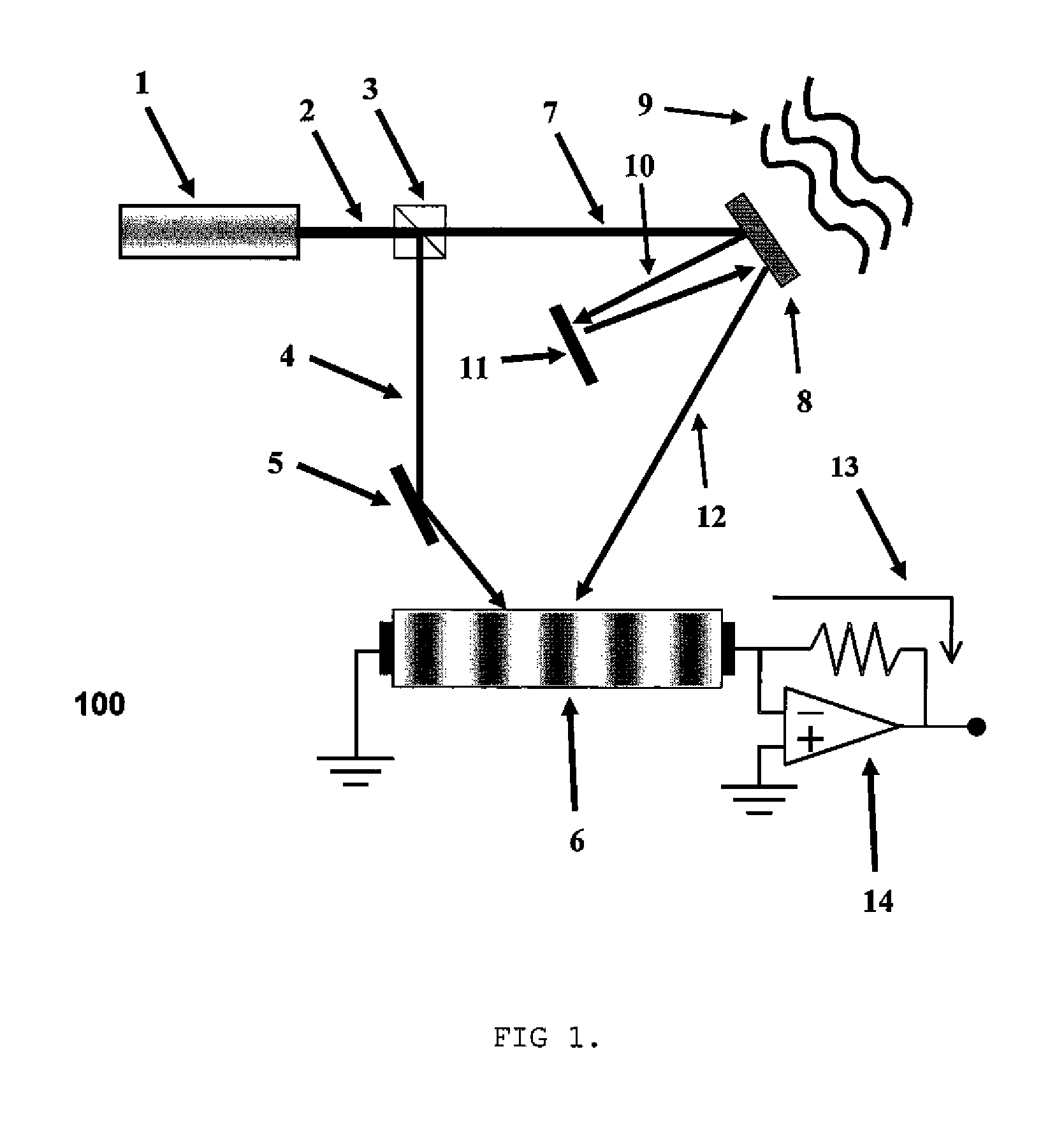
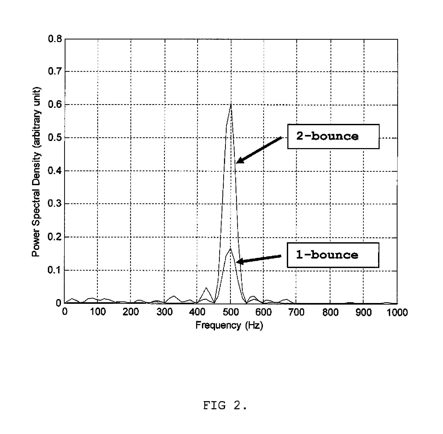
[0025]Using the preferred embodiment shown in FIG. 1, with a pulsed laser, a 1-bounce configuration was compared to a 2-bounce configuration, to monitor the surface vibrations of a mirror being agitated sinusoidally at the frequency of 500 Hz, with a surface displacement of 3.2 nanometers (nm). The output signal strength detected by the invention configured in the 1- and 2-bounce configurations and expressed in terms of power spectral density, was plotted; which plots are depicted in FIG. 2. FIG. 2 shows clearly that the invention configured in the 2-bounce embodiment generated an output signal strength that is a factor of 22=4 times greater than that when the invention was configured in the 1-bounce embodiment, a result predicted in Equations (1, 5).
example 2
[0026]The advantages of enhanced output signal strength and improved detection signal-to-noise ratios for the subject invention when used to monitor the vibrations of pressure-sensing diaphragm are further demonstrated in FIG. 3, which depicts the output signal strength from the preferred embodiment of the subject invention as shown in FIG. 1, using a pulsed laser, and alternative 3-, 5-, and 6-bounce configurations. As predicted by Equations 1 and 5, the increase in output signal strength in proportion to the square of the total number of bounces made by the sensing light beam onto the pressure sensing diaphragm is obviously shown. Thus, simply by increasing the number of bounces, the invention is able to boost its detected output signal strength without resorting to time-consuming averaging or amplifying the noise floor, resulting in better detection sensitivity in sensing the pressure waves as well as improved signal-to-noise ratios in those measurements.
example 3
[0027]An unexpectedly large improvement in detection sensitivity is shown in FIG. 4, using the preferred embodiment of FIG. 1, with a pulsed laser, and a 23-bounce configuration. In this example, the pressure-sensing diaphragm was vibrating at the frequency of 500 Hz and the very minute surface displacement of merely 40 pm (4×10⁻¹¹ meter). The dotted trace was taken with a 4096-point data window (˜1.8 sec time window width) while the solid curve was obtained over a 20,000-point data window (˜8.7 sec data window width, assuming a steady laser pulse repetition rate of roughly 2.3 kHz), leading to finer frequency resolution. The minor peak in the solid trace was caused by the sudden shift in laser repetition rate during the longer data acquisition time period. The inset shows the same spectra in logarithm scales to facilitate the comparison between the detected signal peak strength and the adjacent noise floor which further illustrates the detection sensitivity of this invention when c...
PUM
 Abstract
Description
Claims
Application Information