
Hermetically sealed capacitor assembly

a capacitor and hermetically sealed technology, applied in the direction of hermetically sealed casings, electrical apparatus casings/cabinets/drawers, casings/cabinets/drawers details, etc., can solve the problems of poor conductivity of conductive polymers at high temperatures, performance degradation, and poor stability of conductive polymers

Active Publication Date: 2012-01-10
KYOCERA AVX COMPONENTS CORP
View PDF97 Cites 54 Cited by
  • Summary
  • Abstract
  • Description
  • Claims
  • Application Information

AI Technical Summary

Benefits of technology

The present invention is about a capacitor assembly that includes a ceramic housing and a conductive polymer cathode. The assembly is sealed with a lid in the presence of an inert gas. The technical effect of this invention is to provide a reliable and durable capacitor assembly that can withstand high temperatures and pressure, and has good electrical performance.

Problems solved by technology

Unfortunately, however, the stability of the conductive polymer is poor at high temperatures due to its tendency to transform from a doped to an un-doped state, or vice versa.
As a result of the transformation, the conductivity of the polymer may decrease, which directly affects the capacitance and ESR and leads to performance degradation.

Method used


Image

  • Hermetically sealed capacitor assembly
  • Hermetically sealed capacitor assembly
  • Hermetically sealed capacitor assembly

Examples


example 1

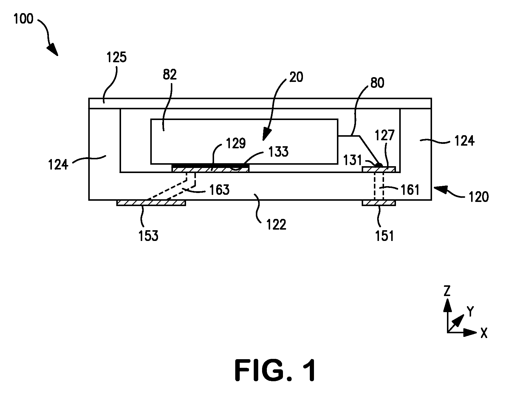
[0042]70,000 μFV / g tantalum powder (HC Starck) was pressed into pellets. Anodic oxidation was then carried out in an aqueous solution containing phosphoric acid. The voltage was chosen to obtain a targeted capacitance of 33 μF at a rated voltage of 10.0V. After anodic oxidation, the pellets were coated with a PEDT conductive polymer layer, a graphite coating and a silver coating by conventional technology known to the skilled in art. The capacitor body had a size of 2.44 mm×1.78 mm×0.68 mm.

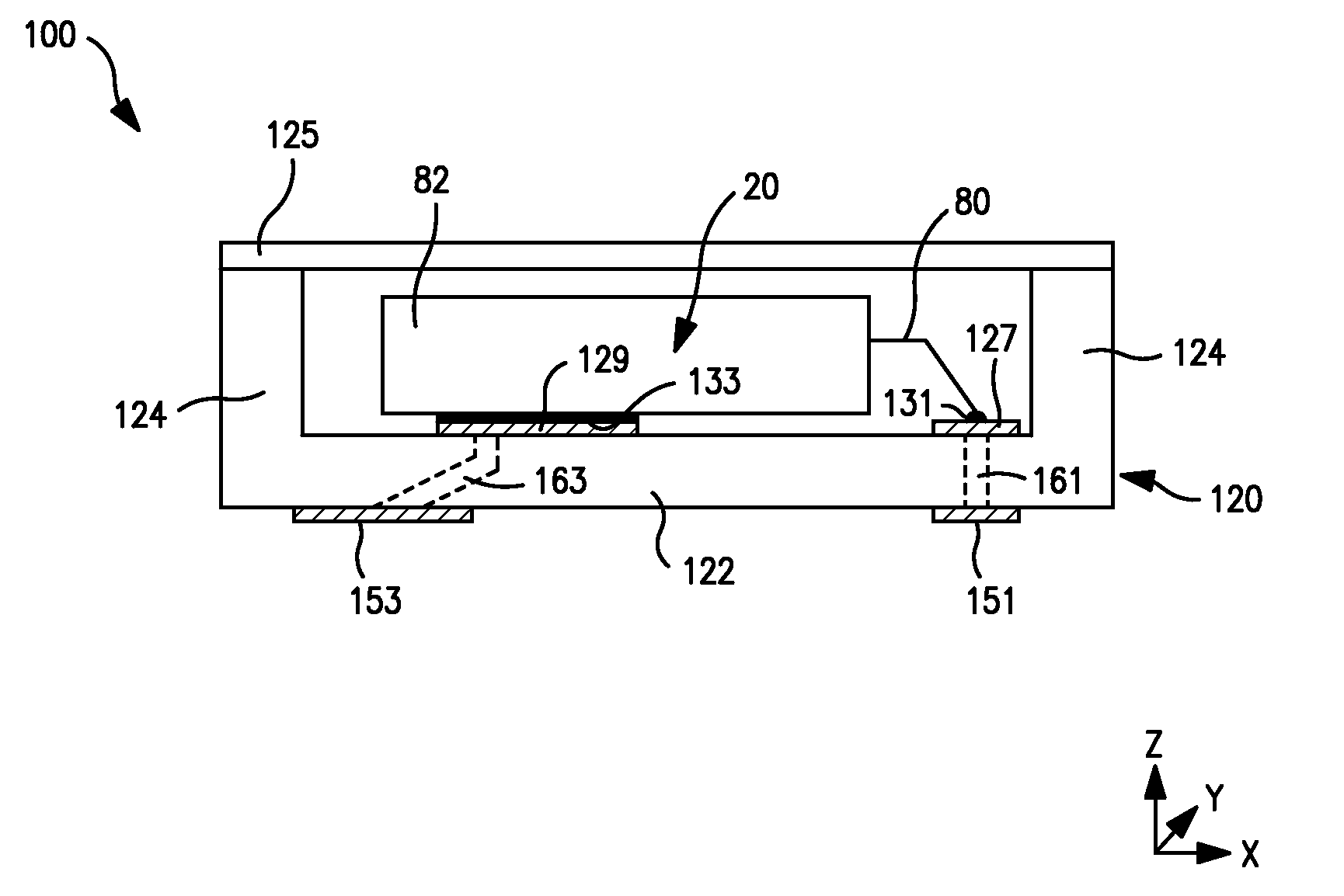
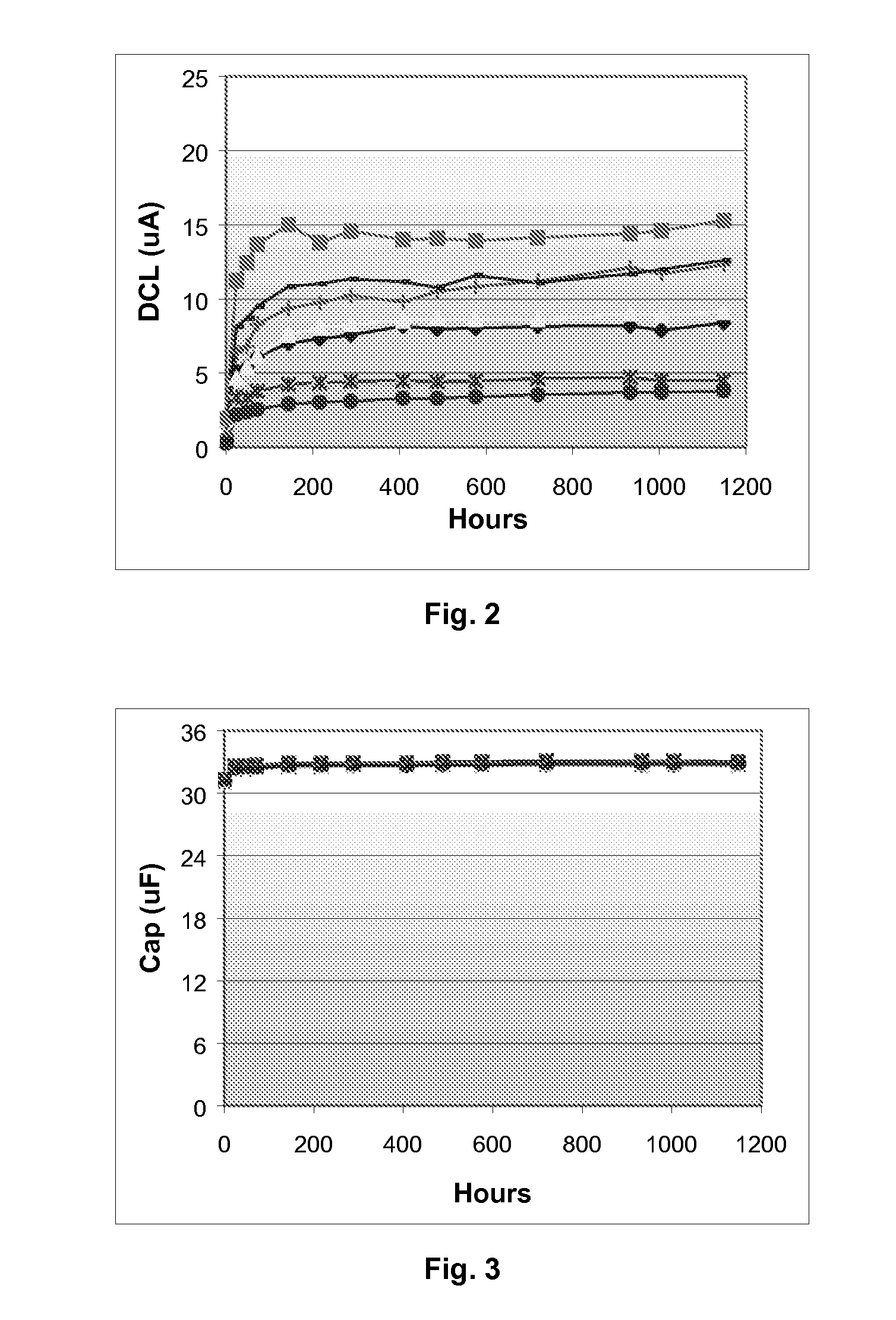
[0043]A ceramic container was also obtained Kyocera America, Inc. of San Diego, Calif. under the name “Cap Pak.” For attachment of the tantalum capacitor inside the ceramic container, a silver-loaded epoxy adhesive (Thermoset K 611-14, Lord Corporation) was employed. The lead wire (tantalum) of the capacitor was first glued to a conductive trace inside the container and thereafter a portion of the capacitor was glued to another conductive trace. The resulting assembly was heated in a convection ov...

example 2

[0045]Capacitor assemblies were prepared as described in Example 1, except that the parts were placed in air at 175° C. Testing was performed on a weekly basis as described in Example 1. The results are shown in FIGS. 5-7. Similar to Example 1, no significant degradation was found.

example 3

[0046]Capacitor assemblies were prepared as described in Example 1, except that the parts were placed in air at 200° C. Testing was performed on a weekly basis as described in Example 1. The results are shown in FIGS. 8-10. Similar to Example 1, no significant degradation was found.


PUM

PropertyMeasurementUnit
series resistanceaaaaaaaaaa
densityaaaaaaaaaa

Abstract

A capacitor assembly that includes a conductive polymer electrolytic capacitor that is enclosed and hermetically sealed within a ceramic housing in the presence of an inert gas is provided. Without intending to be limited by theory, the present inventors believe that the ceramic housing is capable of limiting the amount of oxygen and moisture supplied to the conductive polymer of the capacitor. In this manner, the conductive polymer is less likely to oxidize in high temperature environments, thus increasing the thermal stability of the capacitor assembly.

Description

BACKGROUND OF THE INVENTION[0001]Electrolytic capacitors (e.g., tantalum capacitors) are increasingly being used in the design of circuits due to their volumetric efficiency, reliability, and process compatibility. For example, one type of capacitor that has been developed is a solid electrolytic capacitor that includes an anode (e.g., tantalum), a dielectric oxide film (e.g., tantalum pentoxide, Ta2O5) formed on the anode, a solid electrolyte layer, and a cathode. The solid electrolyte layer may be formed from a conductive polymer, such as described in U.S. Pat. No. 5,457,862 to Sakata et al., U.S. Pat. No. 5,473,503 to Sakata, et al., U.S. Pat. No. 5,729,428 to Sakata, et al., and U.S. Pat. No. 5,812,367 to Kudoh, et al. Unfortunately, however, the stability of the conductive polymer is poor at high temperatures due to its tendency to transform from a doped to an un-doped state, or vice versa. As a result of the transformation, the conductivity of the polymer may decrease, which d...

Claims


Application Information

Patent Timeline
Patent Type & Authority Patents(United States)
IPC IPC(8): H01G4/228H05K5/06H01G9/00H01G9/10
CPCH01G2/12H01G9/15H01G11/48H01G2/06H01G11/56H01G9/08Y02E60/13H01G9/012Y10T29/417H01G9/004H01G9/042
Inventor RAWAL, BHARATNING, GANGJONES, BRADYSEBALD, ZEBBIE LYNNZEDNICEK, STANISLAVSITA, ZDENEK
Owner KYOCERA AVX COMPONENTS CORP
Learn More