Vehicle body with a curved metal plate floor

a technology of metal plate floor and vehicle body, which is applied in the direction of loading-carrying vehicle superstructure, superstructure subunit, transportation items, etc., can solve the problems of large cost of truck body floor repair, large amount of supporting beams, and large volume of mining truck body, so as to reduce the radius of curvature and increase the curvature. , the effect of increasing the flexing of the floor pla

Inactive Publication Date: 2012-01-17
DICKERSON ALAN WILLIAM
View PDF8 Cites 0 Cited by
  • Summary
  • Abstract
  • Description
  • Claims
  • Application Information

AI Technical Summary

Benefits of technology

[0077]For example, the unsupported length may be at least 6 times the diameter of the member. The long unsupported length allows flexure of the tensile members to help accommodate any changes of alignment that may occur and to add to the flexibility of the floor system. A long unsupported length of the tensile members increases the vertical movement of the floor plate as the vertical loading on the floor plate changes. Increased vertical movement of the floor plate assists with freeing of sticky materials that would otherwise accumulate around the corners of the load carrying body.
[0081]The tensile members may bear against pivoting members so as to minimise the transmission of bending loads into the tensile members. A pivoting member for each outer end of the tensile members will increase vertical movement of the floor plate as the vertical loading on the floor plate changes.
[0083]When the centre-line of the tensile members is offset below the centre-line of the floor plate, the forces from the tensile members generate a bending moment in the floor plate that increases with the off-set and acts to increase the curvature (reduce the radius of curvature) of the floor plate as the load in the tension members increases, that is as the load carried by the floor plate increases. This increased flexing of the floor plate as load is increased will assist with shedding of sticky materials during the load dumping operations, but it will also increase the clearance “C” required to prevent excessive contact between the floor plate and the transverse beams in the supporting structure. Conversely, if the centre-line of the tension members is above the centre-line of the floor plate there will be less change of curvature of the floor plate when the load on the floor plate changes.
[0084]The ability to change the stiffness of the tensile members, the stiffness of the abutment for the tensile members, and the offset of the tensile members relative to the centre-line of the floor plate allows the flexibility of the floor plate to be adjusted by design to achieve the preferred balance between flexibility in the floor plate and the payload centre of gravity height.

Problems solved by technology

Mining truck bodies are typically very large.
In some applications it may be mostly large, hard, sharp cornered and very abrasive rocks.
Furthermore, numerous large supporting beams are required under these floor plates.
This repair work generally necessitates exchange of the truck body with a new or repaired body or that the truck spends a lengthy time in a workshop.
The repair of truck body floors is a significant cost item for many mining trucks.
The disadvantages of the suspended rubber floor are:The initial purchase cost is higher than for an all steel truck body.Frequent re-adjustment of the floor support cables is required (to adjust for permanent stretching that occurs).Intermittent and un-predictable replacement of failed or severely damaged cables is required.Replacement floors are expensive.
Because of the above difficulties, the use of suspended rubber floors has been limited to less than 10% of all mining applications.
Their use is mainly restricted to applications where the improved shedding of sticky materials is very important and / or where the reduction of truck empty weight is particularly critical.
However, in practice the stiffness of the plate (arising from the need to provide a long life against abrasive wear), the high variability in the placement of the loads carried, the use of a single radius of curvature rather than a parabolic curvature, and eccentricity of the load transfer points on the edges of the floor, means that the curved steel floor plate is also subjected to moderate bending loads.
If the curved steel plate floor was rigidly attached to the beams at the base of the side sections of the body, this would prevent the steel plate from functioning as a flexible member and also it would cause strongly varying bending stresses at this joint.
If for example the attachment was some form of welded connection, besides destroying the desired flexibility in the floor plate, the varying bending stresses in the welded joint would be likely to cause fatigue failures in the welded joint.
A welded joint would also make replacement of the floor plate much more difficult, much more time consuming and significantly more expensive.
However, this attachment system suffers from the cost of constructing the supports on the side beam at the base of the sides of the body and the difficulty of aligning the round bar on the beam with the bar on the floor plate during manufacture.
High stress concentrations and subsequent failure problems can occur if the contact between the two bars is strongly irregular.
In mining applications, truck bodies are subject to extreme loading conditions that can cause the floor plate and / or the supporting beams to become distorted.
With the attachment system of FIGS. 2 and 3, it is difficult to remedy this situation and failure of the floor attachment system can occur.
Further, when replacement of the edge-supported curved steel floor plate is required, it is difficult to match the position of the round bar on the side beams to the position of the abutment bar on the new floor plate.
This difficulty can cause extra costs or short life of the floor attachment system after replacement of the floor.
However, to date this type of truck body floor has not been commercially adopted for mining truck or other applications.
The main reasons for non-adoption of this technology are:The cost of manufacturing the attachment system between the floor plate and the frame of the body.The difficulty of achieving a good uniform contact between the abutment bar on the floor plate and the mating round bar on the frame when replacement of the floor plate is required.Uncertainty about the ability of this floor to shed sticky materials.

Method used


Image

  • Vehicle body with a curved metal plate floor
  • Vehicle body with a curved metal plate floor
  • Vehicle body with a curved metal plate floor

Examples


Embodiment Construction

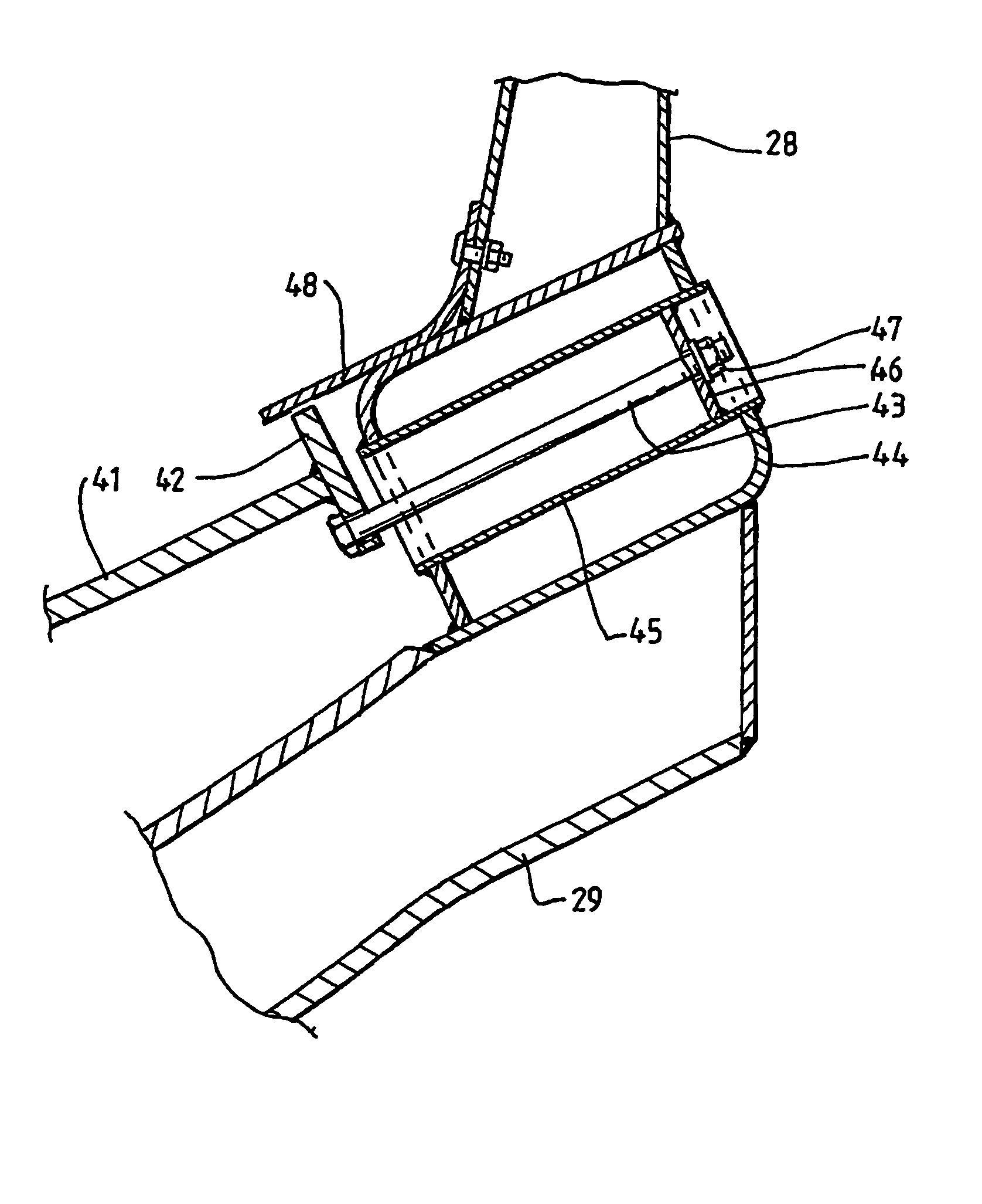
[0092]The embodiment of the floor attachment system shown in FIG. 4 includes an abutment plate 42 that is welded to an edge of a curved steel floor plate 41.

[0093]In addition, the floor attachment system includes a series of tensile members in the form of long bolts 43 (only one of which is shown in the Figure) that pass through holes in the abutment plate 42 and extend through a side beam 44 of a truck body. A series of tubes 45 (only one of which is shown in the Figure) pass through inner and outer sides of the side beam 44 and are welded to the side beam. The bolts 43 pass through the tubes 45 and through holes in a plate 46 that is welded inside each tube 45. A nut 47 on each bolt 43 bears against the associated plate 46. This configuration allows the bolts 43 and the nuts 47 to be recessed inside the tube 45. They are thereby protected from damage from falling rocks, being knocked against other objects, etcetera. The bolts 43 have sufficient threaded length to accommodate manuf...


PUM


Abstract

A system that attaches an edge-supported curved metal plate floor to a load carrying body of a vehicle, such as a truck or rail wagon, is disclosed. The attachment system includes a series of tensile members that are connected directly or indirectly at opposite ends to the plate floor and the body of the vehicle. The tensile members principally transfer forces from the floor plate to the body.

Description

CROSS REFERENCE TO RELATED APPLICATIONS or PRIORITY CLAIM[0001]This application is a national phase of International Application No. PCT / AU2006 / 000427 entitled “Vehicle Body With A Curved metal Plate Floor”, which was filed on Mar. 30, 2006, and which claims priority of the Australia Patent Application No. 05 901546 filed Mar. 30, 2005.FIELD OF THE INVENTION[0002]The present invention relates to a vehicle body with a curved metal plate floor.[0003]The present invention relates particularly, although by no means exclusively, to a system for attaching a curved metal plate floor to a frame of a load carrying body of a vehicle, such as a truck or a rail wagon.[0004]The present invention is described hereinafter particularly in the context of trucks. However, it is emphasised that the present invention is not limited to trucks.[0005]The floor attachment system of the present invention:[0006]Provides for easy installation and replacement of the floor.[0007]Allows for geometric variations ...

Claims


Application Information

Patent Timeline
Patent Type & Authority Patents(United States)
IPC IPC(8): B60J7/00
CPCB60P1/286B61D3/16B61D5/002B61D17/10B62D25/2054B62D33/02
Inventor DICKERSON, ALAN WILLIAM
Owner DICKERSON ALAN WILLIAM
Why Eureka
Try Eureka