Receiving apparatus and method for MIMO system

a technology of receiving apparatus and mimo, which is applied in the field of mimo system receiving apparatus, can solve the problems of delay spray, too fragile mimo system, and increase in complexity of equalizer, so as to shorten the delay time taken, remove interference between spatial streams, and reduce computational complexity

a technology of receiving apparatus and mimo, which is applied in the field of mimo system receiving apparatus, can solve the problems of delay spray, too fragile mimo system, and increase in complexity of equalizer, so as to shorten the delay time taken, remove interference between spatial streams, and reduce computational complexity

US8107563B2Inactive Publication Date: 2012-01-31ELECTRONICS & TELECOMM RES INST

Image

  • Receiving apparatus and method for MIMO system
  • Receiving apparatus and method for MIMO system
  • Receiving apparatus and method for MIMO system

Examples


Embodiment Construction

[0031]The advantages, features and aspects of the invention will become apparent from the following description of the embodiments with reference to the accompanying drawings, which is set forth hereinafter.

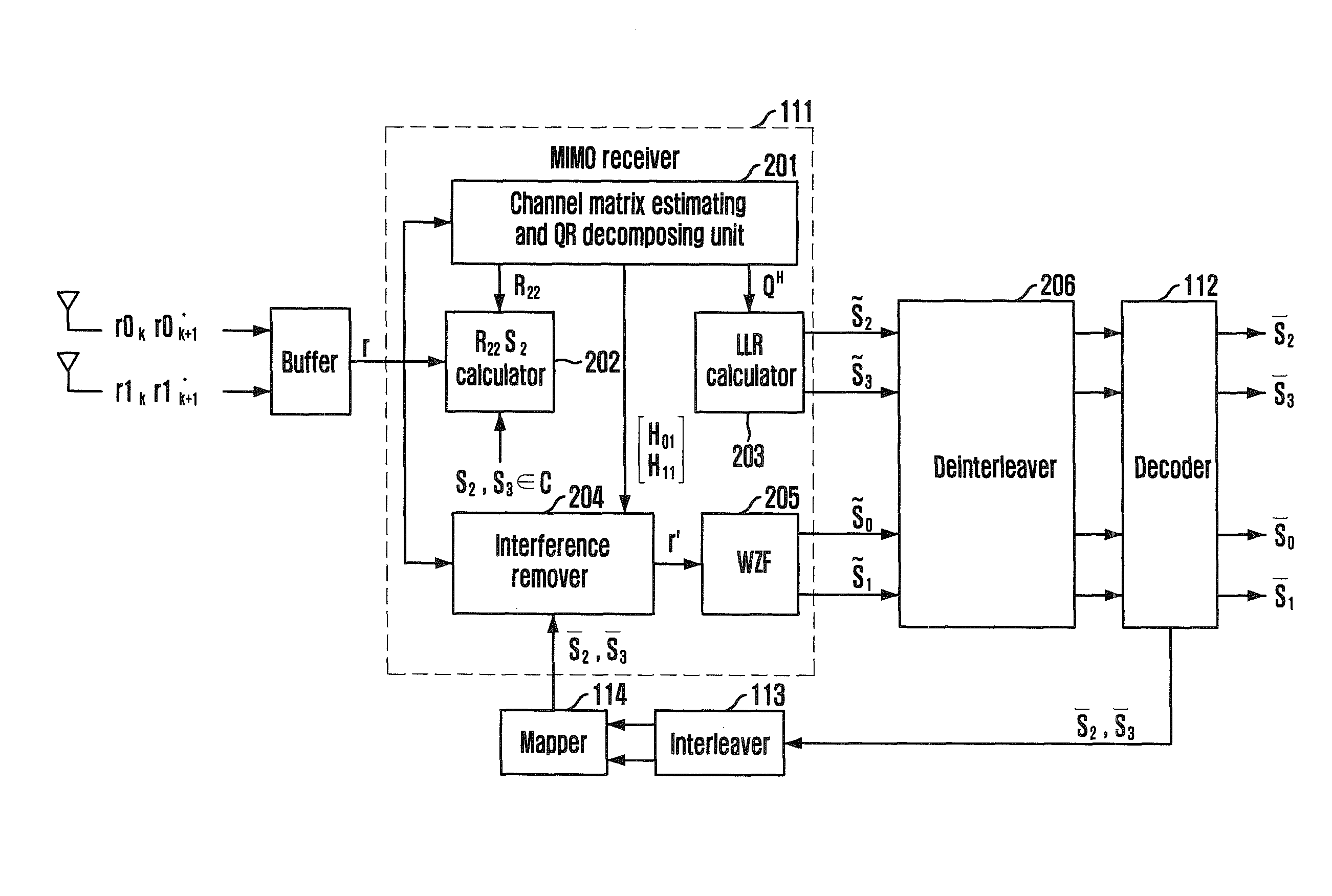
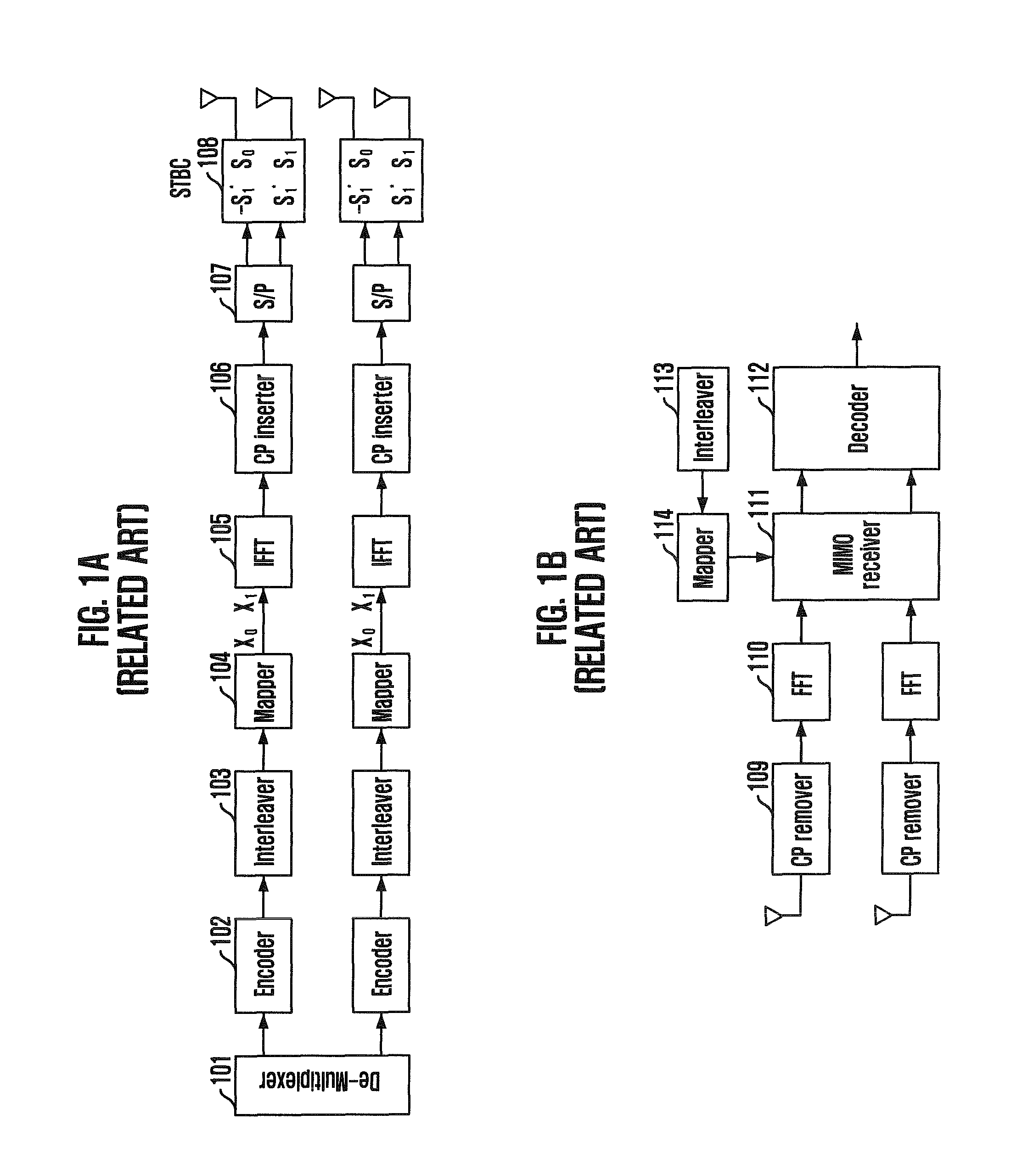
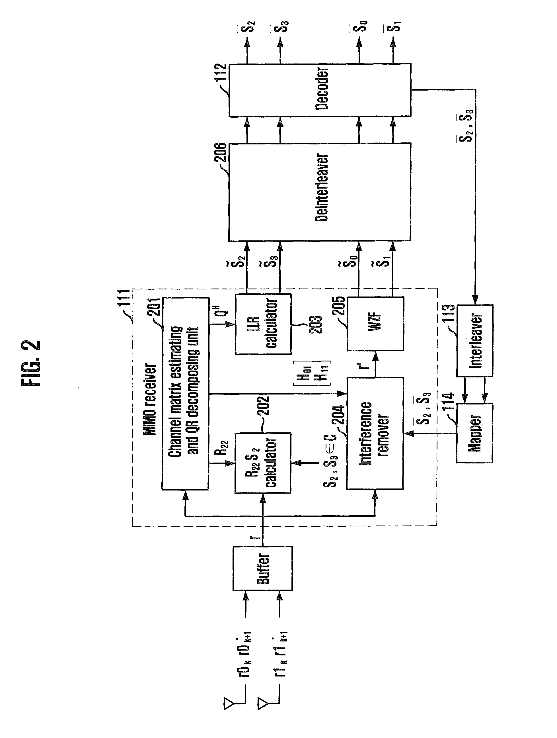
[0032]In case of using four transmitting antennas and two receiving antennas as shown in FIGS. 1a and 1b, a space-time diversity coding process is performed in a time domain after IFFT. The space-time diversity coding process, introduced by Alamouti, can be expressed as Eq. 1.

[0033]x⁡(n,n+1)=[x0⁡(n,n+1)x1⁡(n,n+1)x2⁡(n,n+1)x3⁡(n,n+1)]=[s0-s1*s1s0*s2-s3*s3s2*]Eq.⁢1

[0034]In Eq. 1, a matrix x(n,n+1) means that four symbols s0, s1, s2, and s3 are transmitted for about 2 symbol times. A row of a matrix x denotes a time domain, and a column thereof denotes transmission of each antenna in FIGS. 1a and 1b. A transmitting apparatus shown in FIG. 1a uses four transmitting antennas. The transmitting apparatus transmits four symbols at a first symbol time without modifying phases thereof. At ...


PUM


Abstract

Provided are a receiving apparatus for a multiple input multiple output (MIMO) system and a method thereof. The receiving apparatus includes a QR decomposing unit for calculating a single (Q) matrix vector and an upper triangle (R) matrix vector for a receiving signal vector; a first symbol estimation unit for estimating predetermined symbols using the calculated Q matrix vector and R matrix vector; a log likelihood ratio (LLR) calculating unit for calculating log likelihood ratios of unit bits for the estimated symbols; an interference removing unit for receiving a decoded signal that is decided using the calculated log likelihood ratios and removing interference from the receiving signal vector; and a second symbol estimation unit for linearly estimating remaining symbols for the interference removed signal.

Description

CROSS-REFERENCE TO RELATED APPLICATIONS[0001]The present invention claims priority of Korean Patent Application No. 10-2007-0133529, filed on Dec. 18, 2007, which is incorporated herein by reference.BACKGROUND OF THE INVENTION[0002]1. Field of the Invention[0003]The present invention relates to a receiving apparatus for a multiple input multiple output (MIMO) system and a method thereof; and, more particularly, to a receiving apparatus and a method thereof for improving a signal detection performance with computational complexity reduced using linear and nonlinear receiving schemes together when a receiving signal is detected in a double space time block code-orthogonal frequency division multiplexing (STBC-OFDM) system which is one of MIMO-OFDM technologies.[0004]This work was supported by the IT R&D program of MIC / IITA [2006-S-014-02, “Development of IEEE 802.11n Modem & RF Chip-sets with Data Rate 200 Mbps”].[0005]2. Description of Related Art[0006]It is a requirement of a wirele...

Claims


Application Information

Patent Timeline
31 Jan 2012
Publication
US8107563B2
IPC
H04L27/14
CPC
H04B7/0851; H04L1/0048; H04L1/0631; H04L25/067; H04B7/0669; H04L27/2601; H04B7/08
Inventors
YOON, CHANHO; LEE, IL-GU