Plasma reactor

a plasma reactor and reactor technology, applied in the field of plasma reactors, can solve the problems of affecting the continuous operation of processes, affecting the stability of plasma reactors, and affecting the operation of plasma reactors, so as to increase the range of commercial applications of plasma reactors, stable and uniform plasma, and high durability

Inactive Publication Date: 2012-03-06
CM TECH CO LTD
View PDF10 Cites 8 Cited by
  • Summary
  • Abstract
  • Description
  • Claims
  • Application Information

AI Technical Summary

Benefits of technology

[0053]The plasma reactor according to the present invention has high durability and has performance to generate stable and uniform plasma. The plasma reactor according to the present invention has a variety of advantages such as increasing the range of commercial applications of the plasma reactor since the plasma reactor has a structure that allows simple and efficient installation and operation in a system at a position required by the system.

Problems solved by technology

These technologies have been very rarely commercialized and used since aerosol byproducts generated during their processes may be attached to pipes to clog them or to degrade the electric characteristics of the reactor, thereby impeding continuous operation of processes.
Although these reactors are similar to conventional middle or large-size ozone generators available in the market and thus have advantages in that heat generated in the reactors is discharged to the outside to reduce their operating temperature, they have problems in that their size is large compared to the flow rate of gas.
However, in a harmful gas treatment process in which air and exhaust gases containing a large amount of moisture and particulate matter are treated, in contrast to processes of the ozone generator that generates ozone from relatively clean air or oxygen, arc discharges may occur to cause a serious damage to reactors with a cylindrical structure.
If the power of the plasma generator exceeds a specific level, the harmful gas decomposition capability of the plasma generator reaches its limit so that the harmful gas decomposition capability is no longer increased even though more energy is supplied, thus resulting in high power consumption.
In addition, if the applied voltage is too high, electrons concentrate locally in the plasma generation region to increase the possibility of causing arc discharges, thereby further reducing the efficiency.
The limitation may cause a very high thermal stress locally to the dielectric electrodes to break them.
However, electrical vias, which electrically connect the electrodes, must be made of very expensive platinum since both electrical connection and insulation cannot be achieved under conditions such as the co-firing temperature.
This difference results in a thermal mismatch between the bonding layers to cause a local thermal distortion / stress which may separate the layers.
However, the technology failed to solve the fundamental problems such as dielectric cracking, parting line gaps, and split gaps which may occur in use environments of the reactor with serious thermal changes.
Although this technology can ease the thermal stress that may occur locally, it has the following variety of fundamental problems.
Even when the plasma reactor is installed in the case with the optimal shapes or arrangements such as the optimal interval between gaps and the insulation distance, it is difficult to maintain the shapes uniform if both the plasma reactor and the case that applies the surface pressure to it repeat thermal expansion and contraction as the temperature changes and the exhaust gas pressure is constantly and repeatedly applied to the reactor.
Thus, this structure is very inappropriate taking into consideration the environment of using high voltages.
However, this may make it more difficult to secure the reliability of insulation while making the insulation members and the stacking method more complicated.
That is, terminals connected to an external power supply are easily exposed to moisture and particulate matter in the case, thereby easily causing arc or abnormal discharges.
From the viewpoint of their structures, such reactors will have a great weight and will also require high manufacturing costs.
Especially, when the dielectric components are exposed to an environment with rapid temperature changes of exhaust gases as with exhaust gases of engines, the dielectric components are vulnerable to rapid temperature changes so that cracking, breakage, layer separation, and the like occur in reaction electrodes, electrode connectors, and the like, thereby failing to achieve the purpose of the dielectric material for proper control of high voltages.
However, selection of the material may be limited when the selection is made from materials with good electrical characteristics (especially, insulation performance and dielectric strength) that satisfy requirements of the durability, the plasma generation efficiency, and the like.

Method used


Image

  • Plasma reactor
  • Plasma reactor
  • Plasma reactor

Examples


second embodiment

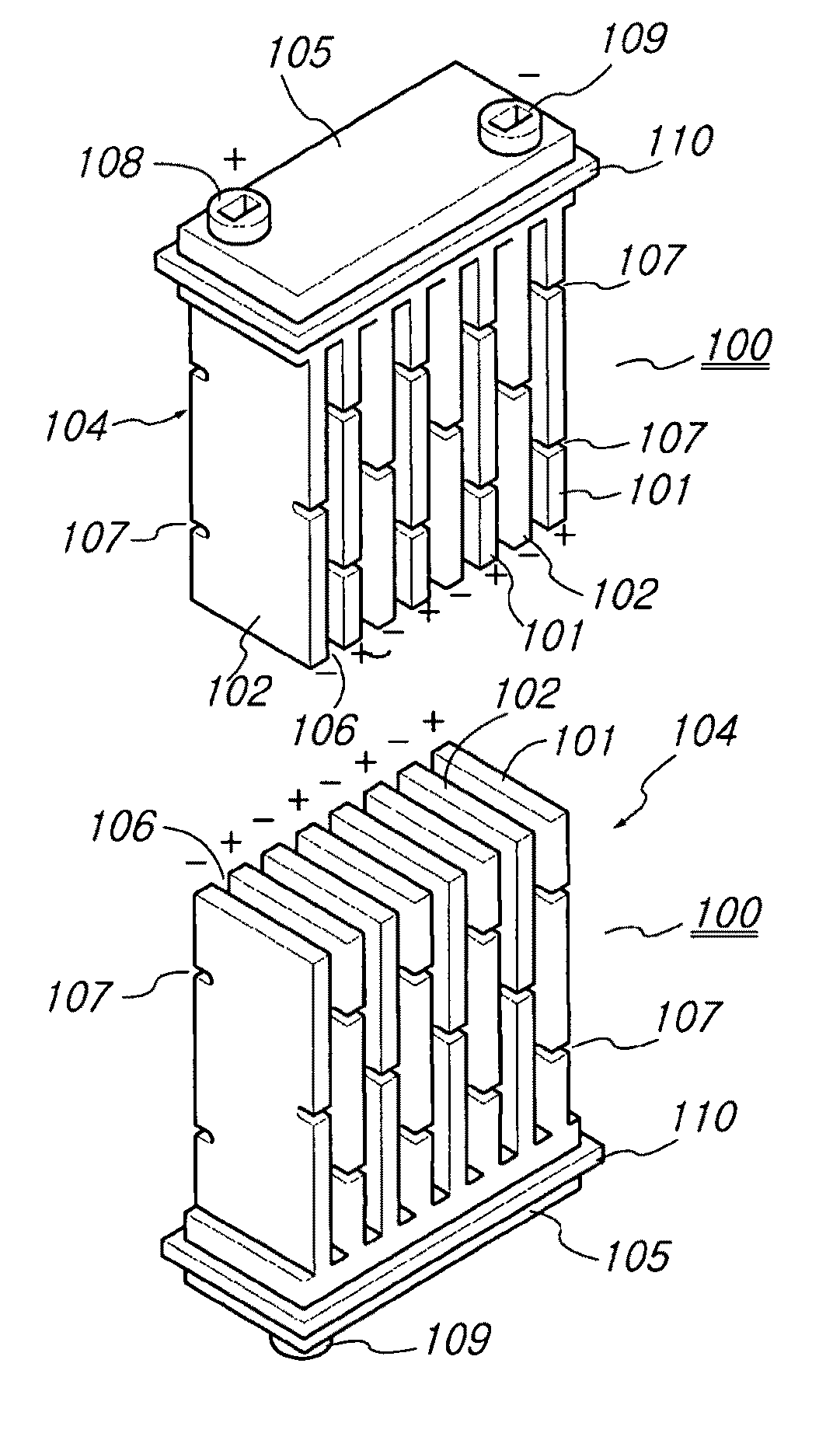
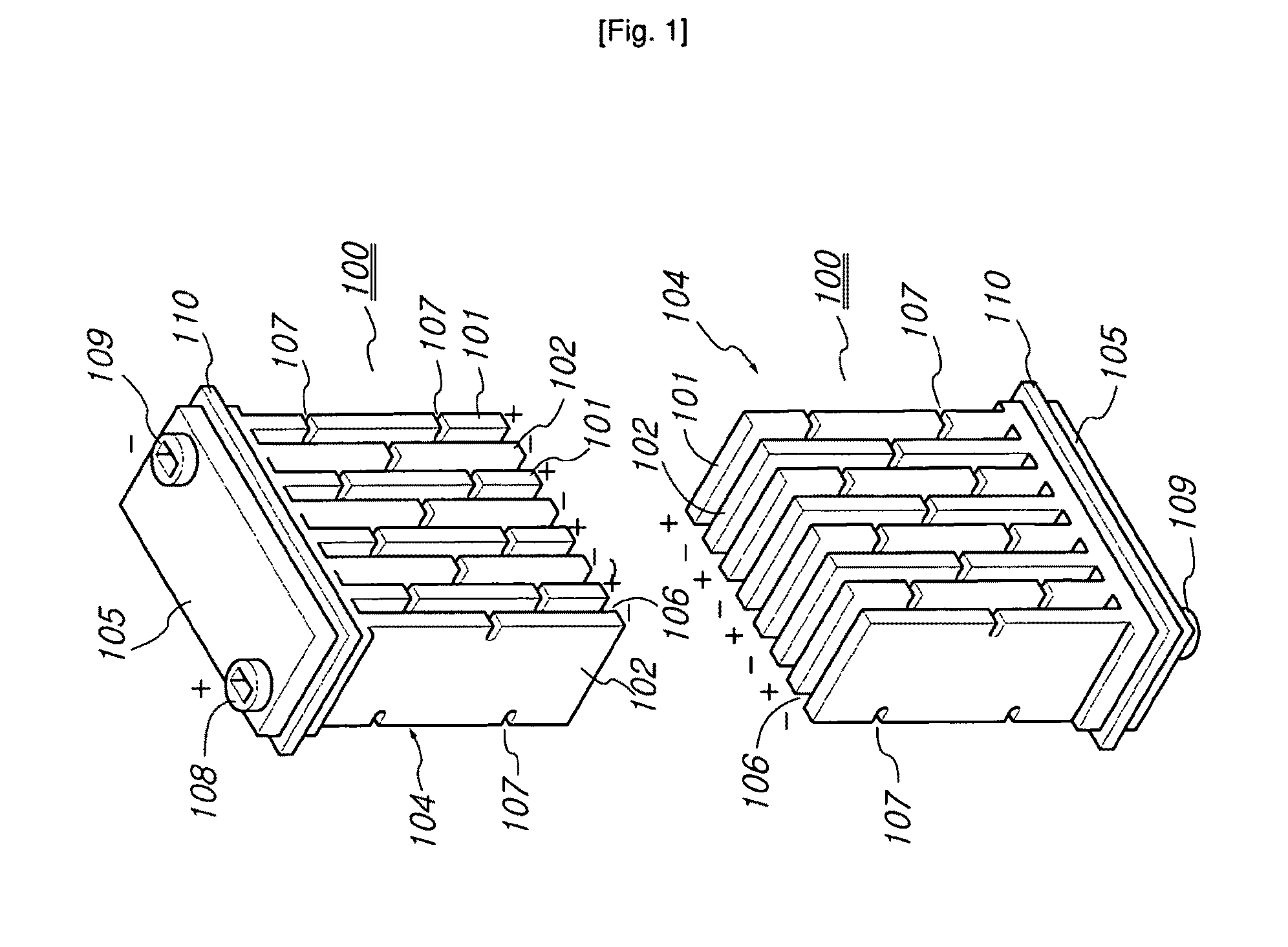
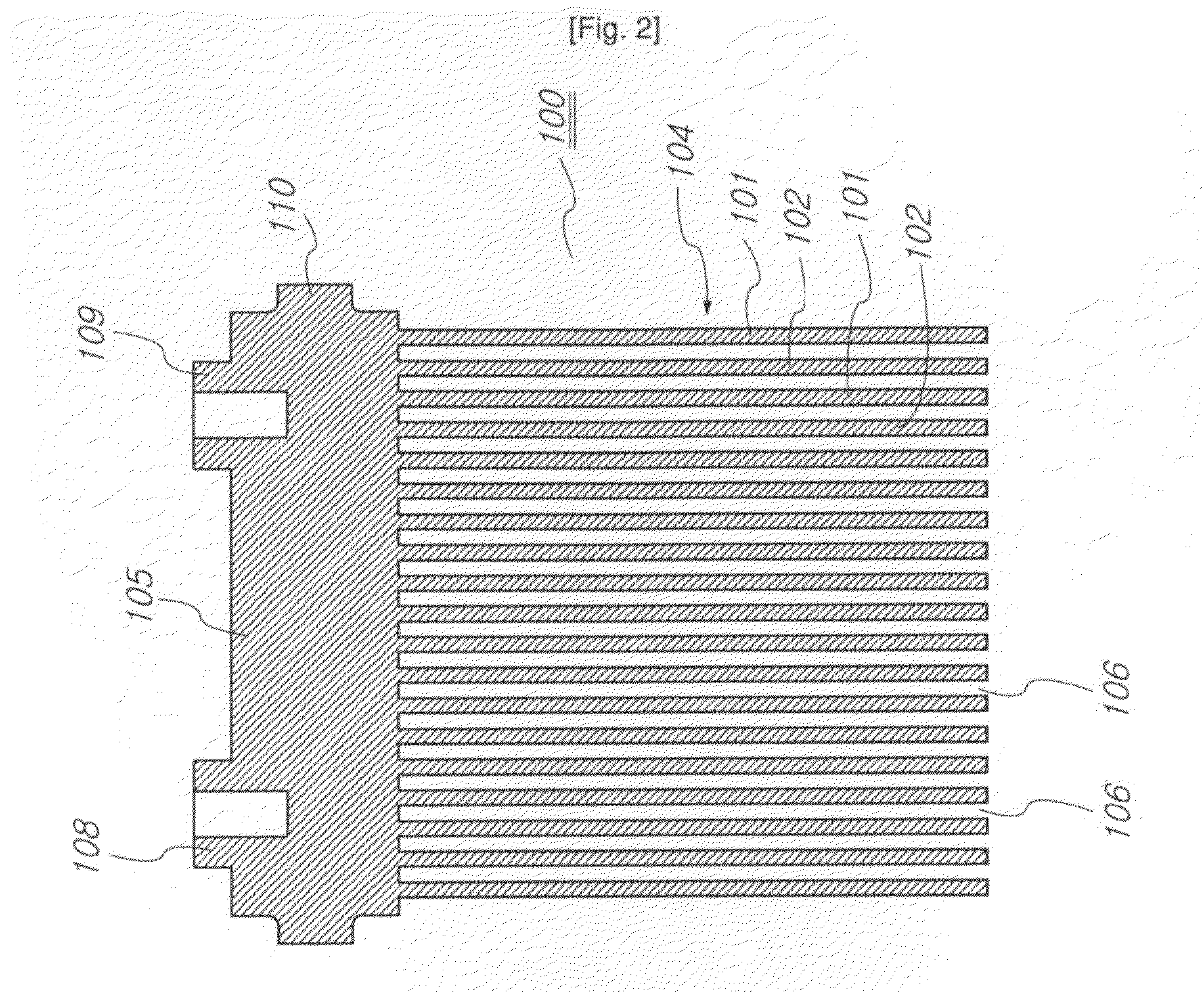
[0175]FIG. 18 is an exploded view of an electrode of a plasma reactor according to the present invention, FIG. 19 is an assembled view of the electrode of the plasma reactor shown in FIG. 18, and FIG. 20 is a cross-sectional view of the plasma reactor when it is combined with a case.

[0176]Reference will now be made to a method for manufacturing a plasma reactor 100 including a stack 104 formed through glass fusion bonding, the stack 104 including external terminals 108 and 109 located at one side according to the second embodiment which shows the features of the present invention. Plus and minus electrodes 101 and 102 individually including external terminals 108 and 109 are manufactured to form the stack 104.

[0177]In one example, a relatively inexpensive electrode material such as W or Mo and an alumina-based ceramic with a high dielectric constant, a high insulation performance, and a high dielectric strength can be used to manufacture dielectric electrodes as plasma generation el...

third embodiment

[0188]FIG. 21 is a front and side cross-sectional view of a plasma reactor according to the present invention.

[0189]Tube-shaped plus and minus electrodes 101 and 102 are provided to construct a plasma reactor 100 in the third embodiment which is another embodiment showing the features of the present invention.

[0190]Specifically, tube-like electrodes 145, each including a conductive electrode layer or a metal rod, are constructed and arranged in one direction. Tube-like electrodes 145 with the opposite polarities are arranged in the same direction at appropriate intervals to allow the generation of plasma. External terminal wires of the tube-like electrodes 145 with the opposite polarities are coupled together at different heights of a stack 104 to provide an appropriate insulation distance between them.

fourth embodiment

[0191]FIG. 22 is a perspective view of a plasma reactor according to the present invention.

[0192]A mixture of flat electrodes 146 and tube-like electrodes 145 is used as the plus and minus electrodes 101 and 102. External terminals of the electrodes with the opposite polarities are coupled together at different heights of a stack 104 to provide an appropriate insulation distance between them.

[0193]FIG. 23 shows a modification of the third and fourth embodiments according to the present invention. Plates 150 having vertical connection electrodes 111 are stacked to construct a reactor body 105. A plasma reactor 100 may be constructed by combining the reactor body 105 and the tube-like (145) or flat plus and minus electrodes 101 and 102 together after inserting, in a vertical direction with respect to the stack direction of the reactor body 105, the plus and minus electrodes 101 and 102 into tube holes 151 and electrode holes 152 formed in the reactor body 105.

[0194]The plasma reactor ...


PUM


Abstract

A plasma reactor has high durability with performance to generate stable and uniform plasma. The reactor has a variety of advantages such as increasing the range of commercial applications since the reactor has a structure that allows simple and efficient installation and operation in a system at a position required by the system. The reactor includes a stack constructed by sequentially stacking plus and minus electrodes and spacers and a reactor body provided at one side of the stack to hold the stack. The plus and minus electrodes are arranged alternately with spacers to define passages through which gas is allowed to pass. Each of the plus and minus electrodes has deformation preventing means to disperse stress of the electrodes and to prevent a local thermal stress caused by thermal expansion and contraction, thereby increasing thermal shock-resistant performance. External terminals for connection to the plus and minus electrodes are provided on the reactor body. A projection is formed on a surface of the reactor body in a direction perpendicular to a stack direction of the stack to allow the reactor to be easily fixed to a case.

Description

CROSS-REFERENCE TO RELATED APPLICATION[0001]This application is a co-pending application which claims priority to PCT Application No. PCT / KR2007 / 003842, filed Aug. 10, 2007, with the Korean Patent Office claiming priority of Korean Patent Application 10-2006-0089186 filed on Sep. 14, 2006, herein incorporated by reference in its entirety.TECHNICAL FIELD[0002]The present invention relates to a plasma reactor (stacked non-thermal plasma reactor (NTPR)), and more particularly to a plasma reactor which is constructed such that a well-insulated high voltage power source supply is connected to electrodes so that it can generate stable and uniform plasma using low power consumption and which also has a structure facilitating the passage of gas through an inner region in which a plasma field is formed.[0003]The plasma reactor has a variety of applications. For example, the plasma reactor can be used as part of a system that reduces or removes harmful gaseous or particulate matter in exhaust...

Claims


Application Information

Patent Timeline
Patent Type & Authority Patents(United States)
IPC IPC(8): B01J19/08B01J19/12F01N3/00
CPCB01D53/323C01B13/10C01B13/11H05H1/24B01D2259/818B01J2219/0875B01J2219/0896F01N3/0892H05H1/46H05H1/466B01D53/32B01D53/92
Inventor MIN, HUNG SIKAN, YOUNG GEUNYANG, SUNG JIN
Owner CM TECH CO LTD
Why Eureka
Try Eureka