Methods of making shaped load-bearing osteoimplant

a technology of osteoimplant and load-bearing bone, which is applied in the field of osteoimplant, can solve the problems of inability to achieve certain clinically desirable shapes and sizes of grafts through cutting and shaping processes, and many structural allografts are never fully incorporated by remodeling and replacement with host tissue, and achieve the effect of sufficient strength

Inactive Publication Date: 2012-03-13
WARSAW ORTHOPEDIC INC
View PDF59 Cites 32 Cited by
  • Summary
  • Abstract
  • Description
  • Claims
  • Application Information

AI Technical Summary

Benefits of technology

[0007]It is an object of the present invention to provide an osteoimplant possessing sufficient strength in a body fluid environment to enable the osteoimplant to bear loads.
[0009]It is yet a further object of the present invention to provide a load-bearing osteoimplant which is osteogenic and thereby promotes new host bone tissue formation within and around the osteoimplant.
[0030]The term “demineralized” as utilized herein refers to bone containing less than about 95% of its original mineral content and is intended to cover all bone particles that have had some portion of their original mineral content removed by a demineralization process. Non-demineralized bone particles provide strength to the osteoimplant and allow it to initially support a load. Demineralized bone particles induce new bone formation at the site of the demineralized bone and permit adjustment of the overall mechanical properties of the osteoimplant.
[0033]The term “osteoinductive” as utilized herein shall be understood to refer to the ability of a substance to recruit cells from the host that have the potential for forming new bone and repairing bone tissue. Most osteoinductive materials can stimulate the formation of ectopic bone in soft tissue.

Problems solved by technology

The range of bone grafts that might be thus prepared is limited by the size and shape limitations of the bone tissue from which the bone graft originated.
Certain clinically desirable shapes and sizes of grafts may thus be unattainable by the cutting and shaping processes, due to the dimensional limitations of the bone.
For some shapes they may also be available only in limited amounts, due to the large variations inherent in the human or animal donor source populations.
Many structural allografts are never fully incorporated by remodeling and replacement with host tissue due, in part, to the difficulty with which the host's blood supply may penetrate cortical bone, and partly to the poor osteoinductivity of nondemineralized bone.
In applications where the mechanical load-bearing requirements of the graft are challenging, lack of replacement by host bone tissue may compromise the graft by subjecting it to repeated loading and cumulative unrepaired damage (mechanical fatigue) within the implant material.

Method used


Image

  • Methods of making shaped load-bearing osteoimplant
  • Methods of making shaped load-bearing osteoimplant
  • Methods of making shaped load-bearing osteoimplant

Examples


example 1

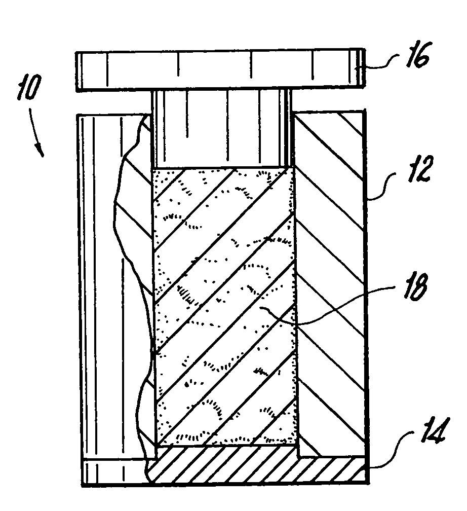
[0150]Elongate bone particles were prepared using a milling machine. Half of the volume of the particles was fully demineralized using two changes of 0.6N HCl acid. The nondemineralized and the fully demineralized particles were then combined together in an aqueous solution containing glycerol and allowed to soak for 4-12 hours at room temperature. The particles were then removed from the solution by straining, and placed into a 28 mm diameter cylindrical press-mold while still moist. The particles were pressed to 10,000 psi for 15 minutes. The resulting compressed pellet was heated in situ in an oven for 4 hours at 45° C. The osteoimplant was then frozen in a −70° C. freezer (1.5 hours), and freeze-dried overnight, after which it was removed from the mold. The bulk density of the osteoimplant produced was 1.34 g / cm3. The height of the osteoimplant was 29 mm. The wet compressive strength of the osteoimplant exceeded 3 MPa.

example 2

[0151]The procedure of Example 1 was used except the ratio of fully demineralized to nondemineralized bone particles was 2:1, the pellet was heated in situ in an oven for 4 hours at 40° C. and the pressure was 2,500 psi. The resulting compressed pellet was cut into two portions and each portion was treated with crosslinking agent: 10% neutral buffered formalin (both dipped and in vapor phase) and 4% Denacol EX313 (a polyepoxy-ether compound available from Nagase America Corp., New York, N.Y.), respectively. In each case, the resulting osteoimplant swelled a little and became stiff, and resistant to manual pressure. The bulk density of the osteoimplant produced was 1.2 g / cm3. The wet compressive strength of the osteoimplant exceeded 3 MPa.

example 3

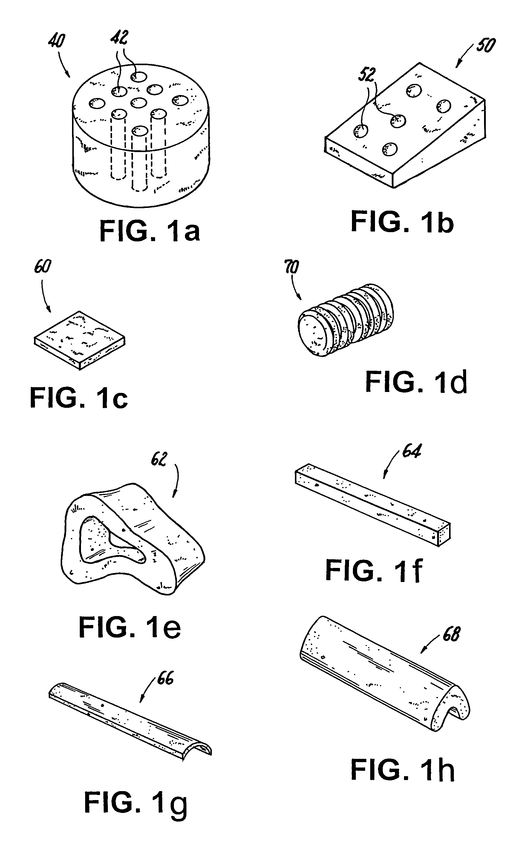
[0152]The procedure of Example 1 was followed except that all of the particles were partially demineralized by using 225 ml of 0.6N HCl and allowing the acid to react to depletion. Additionally, the mold was hexagonal in configuration (with each side of the hexagon measuring 18 mm). After completing the freeze-drying step, the resulting osteoimplant was placed in a bath of 10% neutral buffered formalin and the exposed collagen of the partially demineralized bone particles was allowed to cross-link for 48 hours. The resulting dry osteoimplant was tested mechanically and was found to possess a dry compressive strength of about 85 MPa. The bulk density of the osteoimplant was 1.05 g / cm3.


PUM

PropertyMeasurementUnit
densityaaaaaaaaaa
wet compressive strengthaaaaaaaaaa
median lengthaaaaaaaaaa

Abstract

A load-bearing osteoimplant which comprises a shaped, coherent aggregate of bone particles.

Description

CROSS REFERENCE TO RELATED APPLICATIONS[0001]This application is a continuation-in-part of U.S. patent application Ser. No. 10 / 229,767, filed Aug. 27, 2002, which is a continuation-in-part of commonly assigned U.S. patent application Ser. No. 09 / 911,562, filed Jul. 24, 2001 as a continuation of U.S. patent application Ser. No. 09 / 256,447, filed Feb. 23, 1999, now U.S. Pat. No. 6,294,187.FIELD OF THE INVENTION[0002]This invention relates to osteoimplants and their use in the repair of bone defects and injuries. More particularly, the invention relates to a load-bearing composite osteoimplant which can assume any of a wide variety of configurations, methods for their manufacture and the use of the osteoimplants for the repair of hard tissue.BACKGROUND OF THE INVENTION[0003]Shaped or cut bone segments have been used extensively to solve various medical problems in human and animal orthopedic surgical practice, and their application has also extended to the field of cosmetic and reconst...

Claims


Application Information

Patent Timeline
Patent Type & Authority Patents(United States)
IPC IPC(8): A61B17/56A61F2/30A61L27/36A61L31/00
CPCA61B17/0401A61C8/0012A61C8/0036A61F2/28A61F2/32A61F2/4644A61L27/3608A61L27/3641A61L27/3645A61L27/3683A61L27/3691A61L27/3839A61L27/3847A61L31/005A61B17/72A61B17/742A61B17/80A61B17/86A61B2017/0409A61B2017/0414A61B2017/044A61F2/2803A61F2/2875A61F2/30965A61F2/34A61F2/36A61F2/442A61F2/446A61F2/4611A61F2002/2817A61F2002/2825A61F2002/2835A61F2002/2871A61F2002/2892A61F2002/30004A61F2002/30059A61F2002/30062A61F2002/30113A61F2002/30125A61F2002/30143A61F2002/30146A61F2002/30148A61F2002/30153A61F2002/30154A61F2002/30158A61F2002/30225A61F2002/30237A61F2002/30238A61F2002/30261A61F2002/30266A61F2002/30433A61F2002/30535A61F2002/30561A61F2002/30622A61F2002/30678A61F2002/30785A61F2002/3085A61F2002/3092A61F2002/3095A61F2002/30952A61F2002/30957A61F2002/30962A61F2002/30968A61F2002/3611A61F2002/365A61F2002/3686A61F2210/0004A61F2220/0041A61F2230/0006A61F2230/0008A61F2230/0017A61F2230/0019A61F2230/0021A61F2230/0026A61F2230/0069A61F2230/0082A61F2250/0014A61F2250/0058A61F2250/0071A61F2310/00011A61F2310/00161A61F2310/00173A61F2310/00293A61F2310/00347A61F2310/00365A61L2430/02A61F2002/30677A61F2002/30948B33Y80/00
Inventor BOYCE, TODD M.SHIMP, LAWRENCE A.MANRIQUE, ALBERTWINTERBOTTOM, JOHN M.
Owner WARSAW ORTHOPEDIC INC
Why Eureka
Try Eureka