Method for forming active material on a current collector of negative electrode using feedback process with measuring collector

a negative electrode and current collector technology, applied in the field of batteries, can solve the problems of deterioration of safety, unstable capacity of batteries, thermal instability of lithium, etc., and achieve the effect of stable manufacturing and less variation in properties

Inactive Publication Date: 2012-04-03
PANASONIC CORP
View PDF11 Cites 1 Cited by
  • Summary
  • Abstract
  • Description
  • Claims
  • Application Information

AI Technical Summary

Benefits of technology

[0008]In a method for manufacturing a negative electrode for a battery in accordance with the present invention, an active material layer including a metallic element M and an element A that is at least any one of oxygen, nitrogen and carbon is formed on a current collector. This active material layer is irradiated with an X ray, and at least one of intensity of a Kα ray of the element A and intensity of a Kα ray of the metallic element M in fluorescent X rays generated from the active material layer is measured. According to this method, when a compound as a negative electrode active material having a high capacity density including the metallic element M and the element A that is at least any one of oxygen, nitrogen and carbon is formed on the current collector, it is possible to judge whether or not the composition of the active material layer is appropriate. Furthermore, by controlling a formation condition on the same line based on the measurement result, the change of the physical value is fed back to the formation condition and the composition of the active material layer can be made appropriate on the spot. Consequently, it is possible to stably manufacture a non-aqueous electrolyte secondary battery having less variation in properties such as capacity.

Problems solved by technology

When the composition of the negative electrode active material varies in this way, since an amount of lithium ions that can be absorbed by a unit weight of the negative electrode active material is changed, the capacity as a battery becomes unstable.
The deposited metallic lithium is thermally unstable, which may deteriorate the safety.
Thus, it is difficult to keep the manufacturing condition constant in the reactive gas phase method.

Method used


Image

  • Method for forming active material on a current collector of negative electrode using feedback process with measuring collector
  • Method for forming active material on a current collector of negative electrode using feedback process with measuring collector
  • Method for forming active material on a current collector of negative electrode using feedback process with measuring collector

Examples


first embodiment

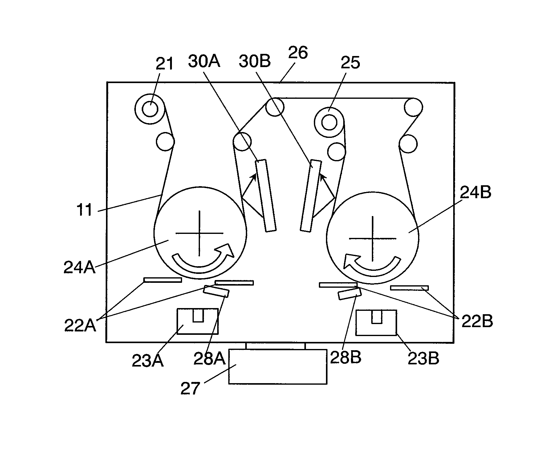
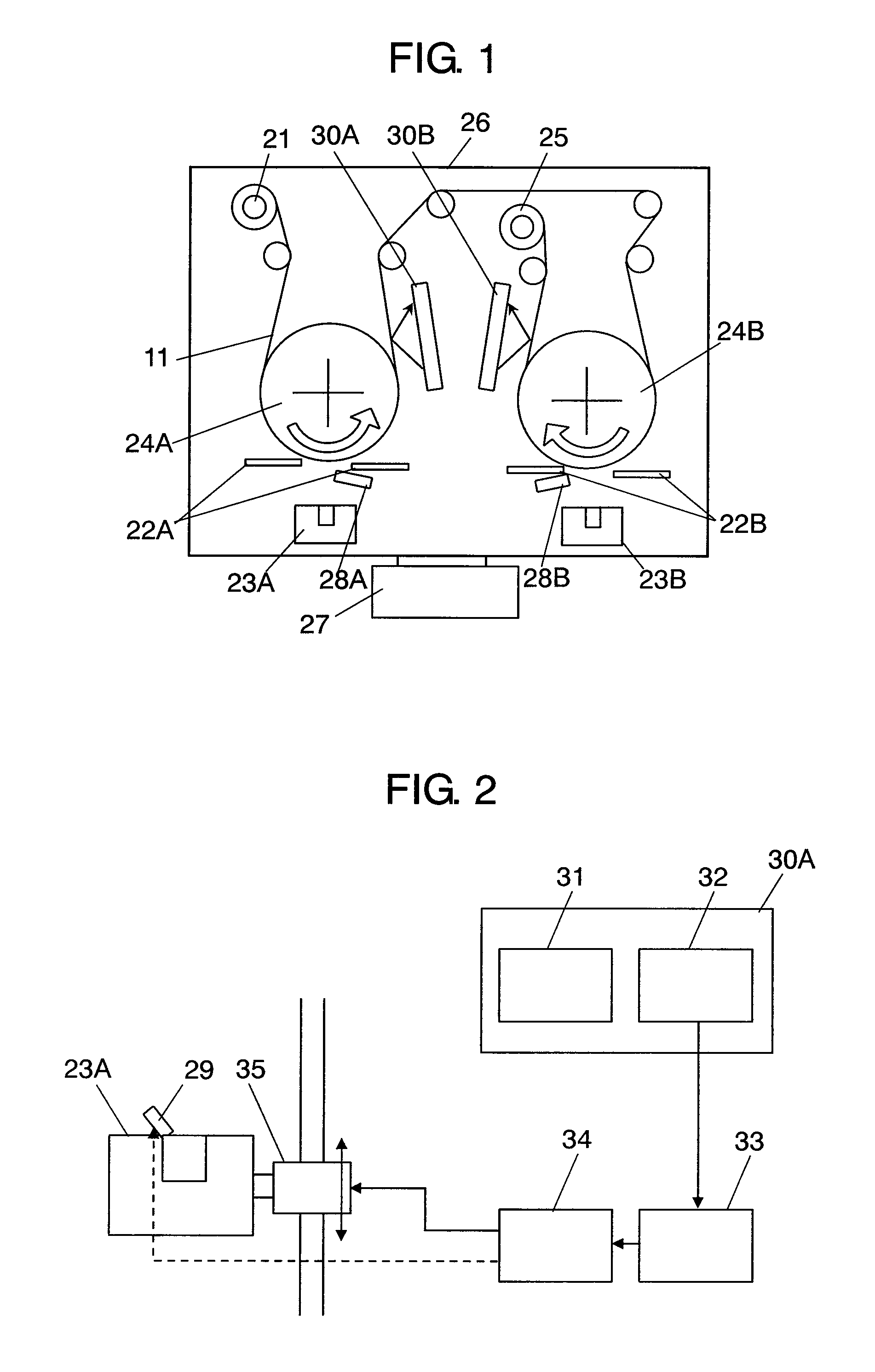
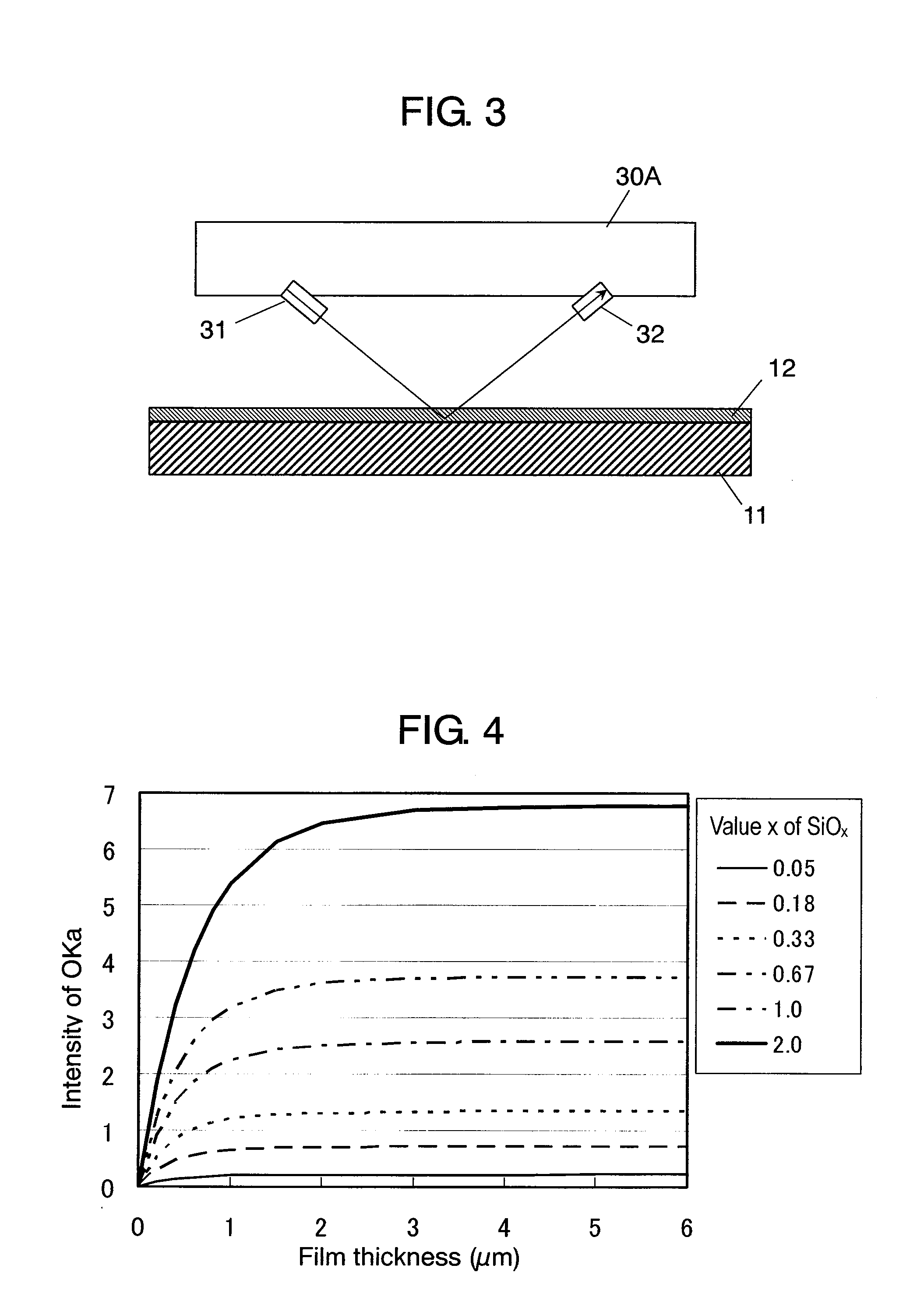
[0029]FIG. 1 is a schematic view showing a configuration of an apparatus for manufacturing a negative electrode for a non-aqueous electrolyte secondary battery in accordance with a first embodiment of the present invention. FIG. 2 is a block diagram showing a detail of a principal part thereof. FIG. 3 is a view showing a configuration around a fluorescent X-ray analyzer that is a first measurement section in FIG. 1.

[0030]In the manufacturing apparatus shown in FIG. 1, current collector 11 is sent from winding-out roll 21 to winding-up roll 25 by way of deposition rolls 24A and 24B. These rolls and vapor deposition units 23A and 23B are provided in vacuum chamber 26. The pressure inside vacuum chamber 26 is reduced by using vacuum pump 27. Vapor deposition units 23A and 23B are units each including a vapor deposition source, a crucible and an electron beam generator. A procedure for forming active material layer 12 as an active material layer of a negative electrode at one side on cu...

second embodiment

[0056]FIG. 8 is a partially perspective view showing an apparatus for manufacturing a negative electrode for a non-aqueous electrolyte secondary battery in accordance with a second embodiment of the present invention and shows around deposition roll 24A. FIG. 9 is a block diagram showing a detail of a principal part thereof. In this embodiment, a configuration of a formation section including deposition roll 24A, winding-out roll 21, nozzle 28A, vapor deposition unit 23A, and the like, is the same as that in FIG. 1. In this embodiment, as the first measurement section, instead of XRF 30A, Fourier transform infrared spectroscopic analyzer (FTIR) 43 is provided. Furthermore, measuring winding-out roll 42 for supplying measuring current collector 41 is provided. Measuring winding-out roll 42 rotates faster than winding-out roll 21. That is to say, measuring current collector 41 is sent faster than current collector 11. A formation section deposits SiOx on current collector 11 and measu...

third embodiment

[0068]FIG. 12 is a partial plan view showing an apparatus for manufacturing a negative electrode for a non-aqueous electrolyte secondary battery in accordance with a third embodiment of the present invention and shows around deposition roll 24A. FIG. 13 is a block diagram showing a detail of a principal part thereof. In this embodiment, a configuration of a formation section including deposition roll 24A, winding-out roll 21, nozzle 28A and vapor deposition unit 23A, and the like, is the same as that in FIG. 1. In this embodiment, instead of XRF 30A, a first measurement section for measuring the thickness of active material layer 12, which includes base roll 52, thickness measurement device 51 and operation section 56, and a second measurement section for measuring the resistance of active material layer 12, which includes a pair of resistance measurement rolls 53 and resistance measurement device 57 are provided.

[0069]When current collector 11 passes on base roll 52, thickness meas...


PUM

PropertyMeasurementUnit
pressureaaaaaaaaaa
thicknessaaaaaaaaaa
densityaaaaaaaaaa

Abstract

In a method for manufacturing a negative electrode for a battery, an active material layer including a metallic element M and an element A that is at least any one of oxygen, nitrogen, and carbon is formed on a current collector. This active material layer is irradiated with an X-ray and at least one of intensity of a Kα ray of the element A and intensity of a Kα ray of the metallic element M in fluorescent X-rays generated from the active material layer is measured.

Description

BACKGROUND OF THE INVENTION[0001]1. Field of the Invention[0002]The present invention relates to a battery, a method and an apparatus for manufacturing a negative electrode of the battery. More particularly, the present invention relates to stabilization of performance of a non-aqueous electrolyte secondary battery using an active material having a high capacity density, for example, silicon (Si) or a Si compound, for a negative electrode.[0003]2. Background Art[0004]A non-aqueous electrolyte secondary battery represented by a lithium ion secondary battery has received attention as a high capacity power source mainly for portable equipment. Recently, in order to further increase the capacity of this battery, development of electrode materials (use of an active material having a high capacity density and reduction of sub-materials) and improvement (for example, thinning) of mechanical components have been actively carried out.[0005]Especially, silicon (Si), tin (Sn), germanium (Ge) a...

Claims


Application Information

Patent Timeline
Patent Type & Authority Patents(United States)
IPC IPC(8): H01M4/02B05D3/00C23C10/10C23C8/00C23C14/10C23C16/10C23C16/24C23C16/00H01M4/68H01M4/66H01M4/58H01M4/13B05D3/06C08J7/18H01M4/139H01M4/1397
CPCH01M4/04H01M4/485H01M4/58H01M4/583H01M4/661H01M10/05H01M2004/027Y02E60/122Y02E60/10
Inventor TAKEZAWA, HIDEHARUSHIRANE, TAKAYUKIFUJIMURA, SHINYAOKAZAKI, SADAYUKIHONDA, KAZUYOSHI
Owner PANASONIC CORP
Why Eureka
Try Eureka