Method and system for analog frequency clocking in processor cores

a processor core and frequency clock technology, applied in the field of data processing systems, can solve the problems of inability to maintain a long-term strategy, inability to transmit high-frequency clocks (>5-10 ghz) for multiple chips comprised of multiple cores, and limited scalability of techniques, so as to minimize latency and achieve the net performance gain of operating each cor

Active Publication Date: 2012-04-17
IBM CORP
View PDF19 Cites 4 Cited by
  • Summary
  • Abstract
  • Description
  • Claims
  • Application Information

AI Technical Summary

Benefits of technology

[0008]Another object of the present invention is to enable optimum frequency performance of each of multiple processor cores independently of the other processor cores.
[0013]The frequency control information is sent to each core as moderate speed (10-100 Mb / s) digital data words thereby avoiding the problems with high-speed analog signal transmission. The frequency control information has high noise immunity and low signal distortion since it is in the form of digital data. The frequency control information is sent as individual control data words (v data) to each core. The data is latched into the core “clock synthesizer memory” from the server SEEPROM, which contains the vital chip data (VCD) for each core in the server. The single system reference oscillator is set at a moderate frequency (10-100 MHz), which is distributed to each core via analog transmission line techniques; phase locked loops (PLL), and re-drive circuits. The analog clock signal frequencies are kept moderate prior to the individual core clock synthesizers to avoid high-speed distortion effects.
[0015]Each core is running asynchronous from each of the other cores and with respect to local cache. It will be appreciated that, once the different regions of a chip are asynchronous, some handshaking / buffering will be required to transfer data between regions, so there will be some added latency. Techniques are known to minimize this latency. Nevertheless, the net performance gain of operating each core at its maximum frequency will be substantial (10-20%).

Problems solved by technology

Also, the increasing difficulty and hardware cost, as well as signal integrity concerns, associated with the transmission of high frequency clocking throughout a multi-chip and multi-core processor server make this an untenable long-term strategy for future server systems.
This technique is limited in scalability due to skin effect, media and connector loss, crosstalk, termination mismatches, etc.
Transmission of high frequency clocks (>5-10 GHz) for multiple chips comprised of multiple cores is not feasible with known board technology and connectors.
Obtaining optimum performance for each core within a multi-core system is not feasible today.
Separate core voltage domains are known and state-of-the-art but they can only serve to optimize the power at the chip level and not obtain optimum core performance.
A server system with separate frequency domains per core is very complicated and is not practiced in the industry.
Spread spectrum clocking used for EMI reduction with multiple oscillators makes “synchronous spreading” very difficult or impossible.
With the growth in the number of cores in multi-core microprocessors, clock-trees also grow into enormous complexity, creating serious chip layout design difficulties and translating into detractors to final product yield and related increase in manufacturing cost.

Method used


Image

  • Method and system for analog frequency clocking in processor cores
  • Method and system for analog frequency clocking in processor cores
  • Method and system for analog frequency clocking in processor cores

Examples


Embodiment Construction

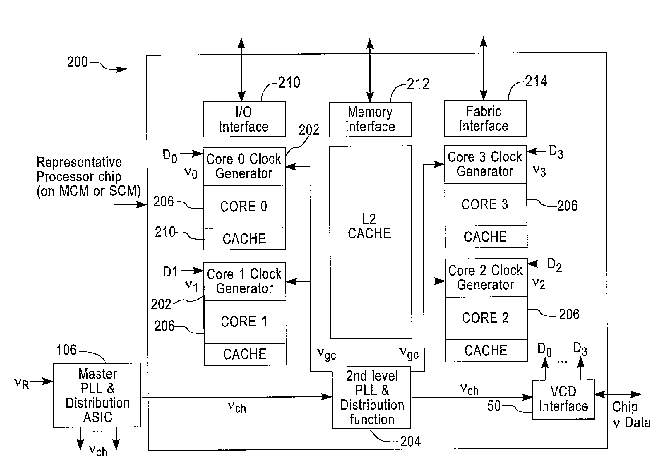
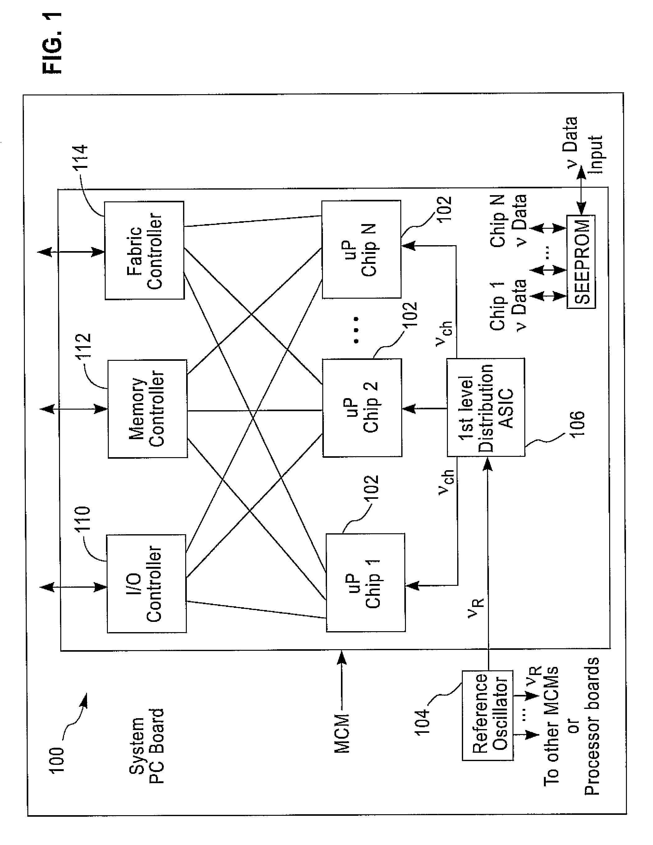
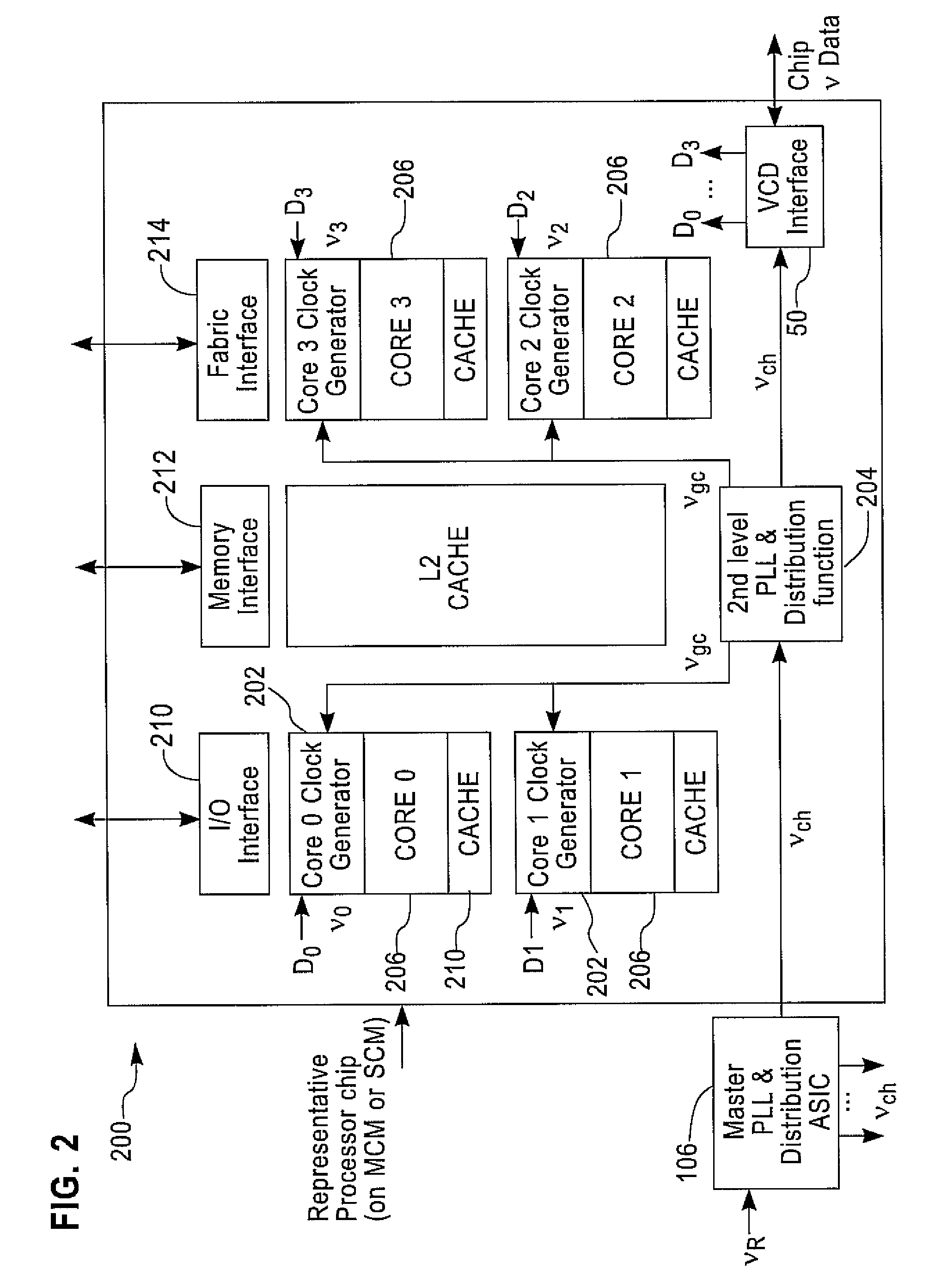
[0023]FIG. 1 illustrates a typical computing Server 100 that is composed of multiple microprocessor (uP) chips (N) 102 which has internal clocking functions (e.g. digital signal processor, DSP, core clock generator, etc.) that utilize the server reference oscillator (vR) as the basic system clock. A Master PLL and distribution ASIC (Application Specific Integrated Circuit) on the MCM or system board multiplies, re-drives, and distributes the reference clock signal to each uP chip in the Multi-chip Module (MCM) or system board. The output of the Master PLL & Distribution ASIC is a chip clock signal (vch) that is distributed throughout the processor chip.

[0024]The reference oscillator 104 clock frequency (νR) is a relatively low frequency (typically 10-100 MHz) such that it can be easily routed throughout the PC board without significant signal degradation yet fast enough to enable feasible up-conversions rates to insure the uP high speed clock (typically 5-10 GHz) is stable and remai...


PUM


Abstract

A method of and system for frequency clocking in a processor core are disclosed. In this system, at least one processor core is provided, and that at least one processor core has a clocking subsystem for generating an analog output clock signal at a variable frequency. Digital frequency control data and an analog signal are both transmitted to that at least one processor core; and that processor core uses the received analog signal and digital frequency control data to set the frequency of the output clock signal of the clocking subsystem. In a preferred implementation, multiple cores are asynchronously clocked and the core frequencies are independently set.

Description

CROSS REFERENCE TO RELATED APPLICATION[0001]This application is related to copending application Ser. No. 11 / 734,375, for “Method and system for Digital frequency Clocking in Processor cores,” filed herewith, the disclosure of which is herein incorporated by reference in its entirety.BACKGROUND OF THE INVENTION[0002]1. Field of the Invention[0003]This invention generally relates to data processing systems, and more specifically, to frequency clocking in processor cores. Even more specifically, in the preferred embodiment, the invention relates to the analog multi-frequency clocking in multi-chip / multi-core processors.[0004]2. Background Art[0005]Servers are beginning to exploit a multiplicity of multi-core processor chips in order to continue to increase performance as processor frequency scaling can no longer meet the industry growth in performance. Also, the increasing difficulty and hardware cost, as well as signal integrity concerns, associated with the transmission of high freq...

Claims


Application Information

Patent Timeline
Patent Type & Authority Patents(United States)
IPC IPC(8): G06F1/12G06F1/00G06F1/04
CPCG06F1/06G06F1/08H03L7/1976
Inventor JACOBOWITZ, LAWRENCERITTER, MARK B.STIGLIANI, JR., DANIEL J.
Owner IBM CORP
Why Eureka
Try Eureka