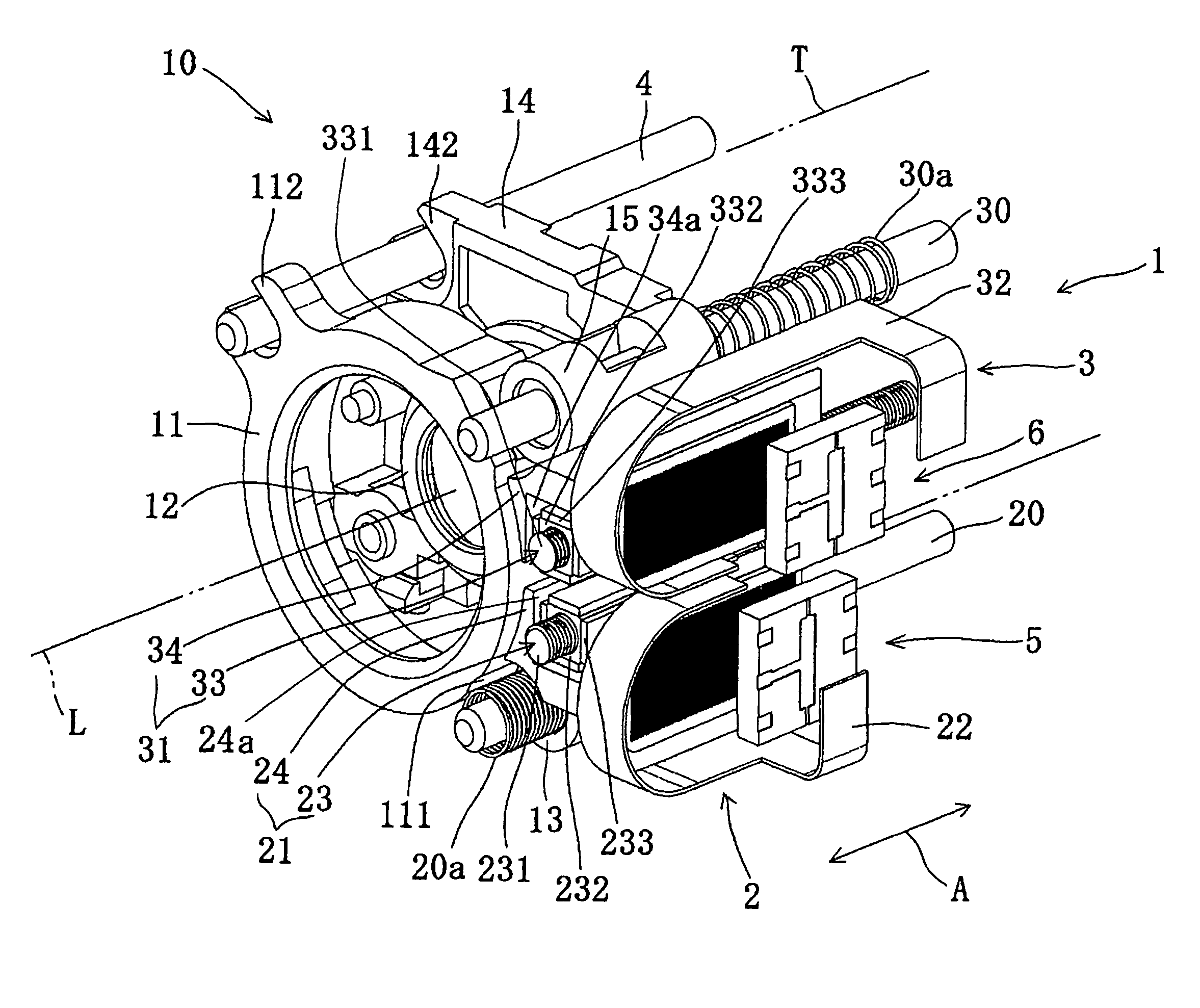
Sliding device composed of combined structure of screw bolt and nut

a combined structure and sliding device technology, applied in the direction of mechanical equipment, instruments, etc., can solve the problems of damage, difficult fine adjustment, and difficult assembly, and achieve the effect of reducing abrasion damage in sliding behavior on both the male thread and the female thread, reducing abrasion damage, and improving the sliding device drastically

Inactive Publication Date: 2012-04-24
TAMRON
View PDF5 Cites 4 Cited by
  • Summary
  • Abstract
  • Description
  • Claims
  • Application Information

AI Technical Summary

Benefits of technology

[0044]In the sliding device of the present invention, abrasion damage in a sliding behavior on both the male thread and the female thread is reduced by effectively reducing abrasion on both the male thread and the female thread to the minimum by managing |H1−H2| between 300 HV0.1 to 350 HV0.1, when Vickers hardness of a metal material constituting the male thread is H1, and Vickers hardness of a metal material constituting the female thread is H2. As a result, longer life and durability as the sliding device can be improved drastically.
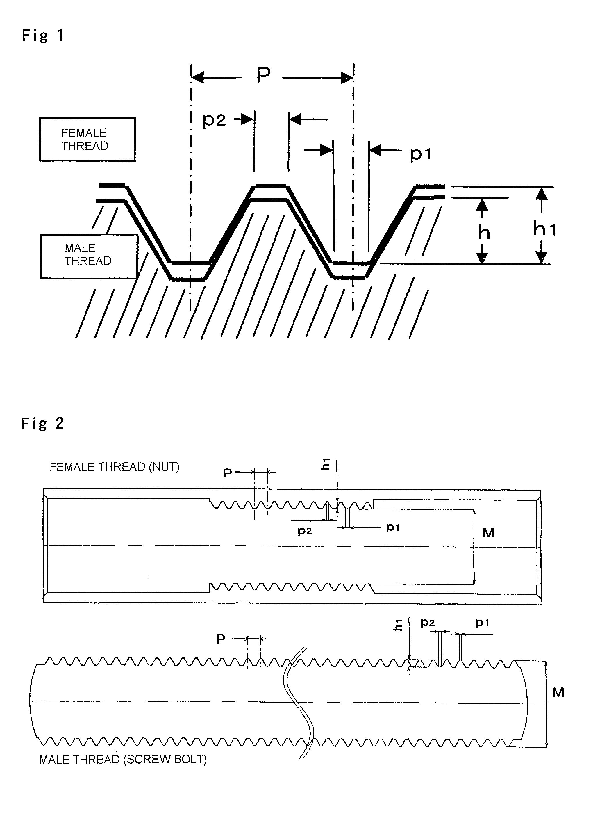
[0045]Also, when the threads formed on the screw bolt and the nut to be the sliding device of the present invention is set at the nominal diameter M of 1.1 mm or less, the pitch P of 0.2 mm or less, the radial length of the screwed portion of 0.05 mm or more, the width of the thread peak portion of 0.015 mm to 0.05 mm, the width of the thread groove portion of the screw bolt is 0.04 mm or less, and the width of the thread groove portion of the nut of 0.03 mm or less, performance of the screw rotation can be smooth and accurate.
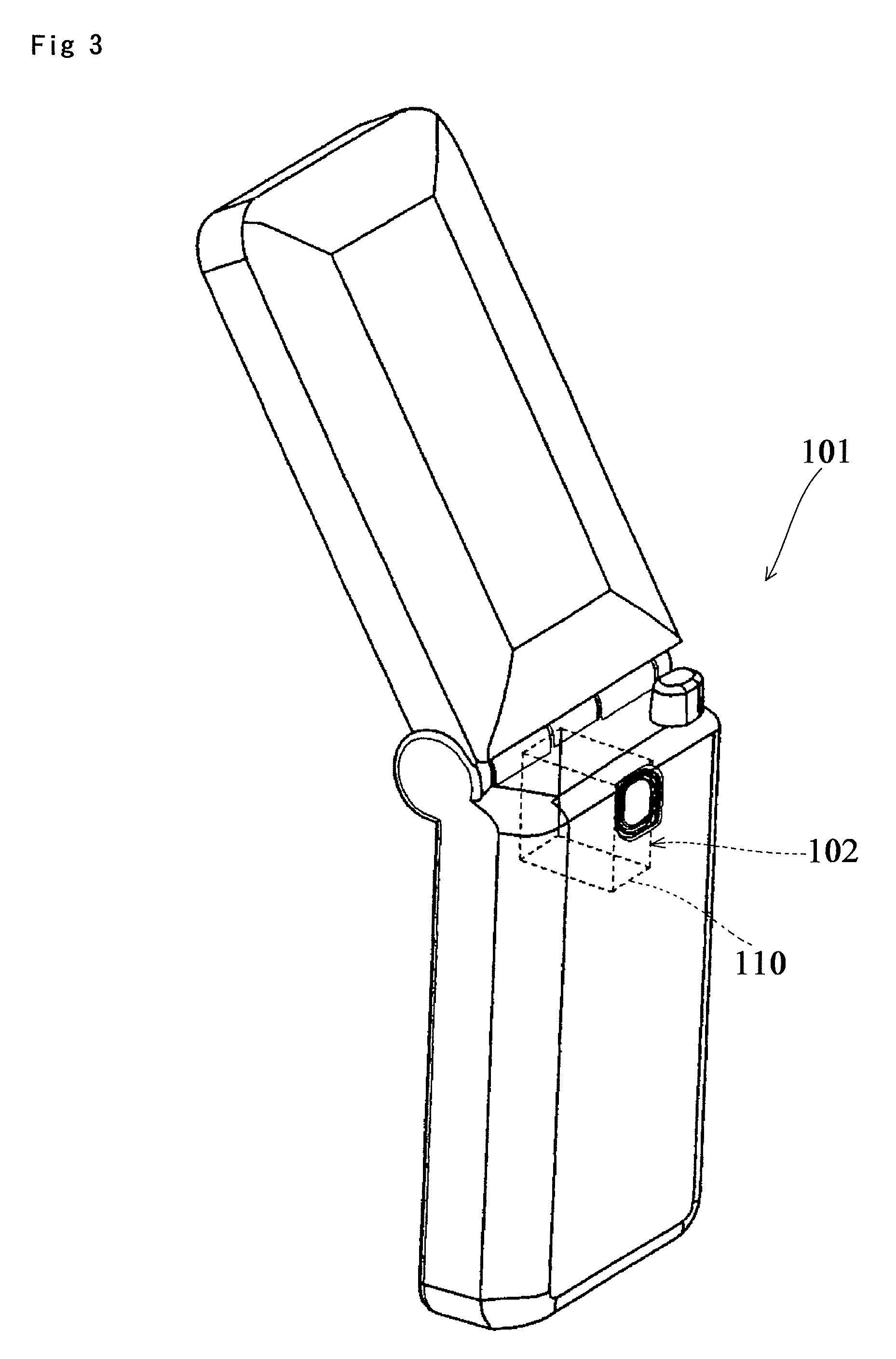
[0046]By using the sliding device of the present invention, the above-mentioned excellent property can be performed in lens driving to result supply of a high-quality camera.

Problems solved by technology

Reasons why the piezoelectric element is used is that when an electromagnetic motor is used, for example, an electromagnetic field generated in a cellular phone may cause an electromagnetic noise to make the size reduction hard and the assembly difficult.
However, because of the quick response, fine adjustment is difficult.
However, a problem in such a case is damage caused by slight relative reciprocal sliding motion, that is, fretting motion.
In the combined structure of the lead screw and the stator, surface damage called fretting wear may easily occur when two faces are slightly slide while in contact.
Taking place of the oxidized abrasion powder may cause back-lash to reduce mechanical accuracy and functions extremely, also which causes vibration and / or noise.
Moreover, adhesion of the abrasion powder might make disassembly and / or repair impossible.
As described above, the phenomenon caused by fretting wear is serious surface damage in the fields of tribology and material strength.
When the repeating stress is put on the contact portion at the same time, fretting fatigue occurs, and fatigue cracks might be generated in a damaged portion, which progresses and results destruction of the member and extremely reduces fatigue strength of the member.
However, in Japanese Patent Application (National Publication of International Patent Application No. 2007-505599), as the materials of the shaft 12 with screw and the screwed nut 16 in the embodiment of the description, the shaft 12 with screw is made of substantially stainless steel, and a brass nut is used for the nut 16 to be engaged with the shaft, but with the combination of the shaft with screw and the screwed nut by the materials disclosed in Japanese Patent Application (National Publication of International Patent Application No. 2007-505599), it is actually difficult to obtain sufficient durability as a sliding device.

Method used


Image

  • Sliding device composed of combined structure of screw bolt and nut
  • Sliding device composed of combined structure of screw bolt and nut
  • Sliding device composed of combined structure of screw bolt and nut

Examples


examples

[0105]Preparation of the screw bolt specimen: In Example shown in Table 1, a material of a martensite stainless steel which has a composition of nickel content of 0.6 wt % or less, chromium content of 12.0 wt % to 18.0 wt %, carbon content of 0.16 wt % to 1.2 wt %, silicon content of 0.15 wt % or less, manganese content of 1.25 wt % or less, phosphorus content of 0.06 wt % or less, sulfur content of 0.15 wt % or less and the control of iron and unavoidable impurities was used in preparation of the screw bolt.

[0106]Preparation of the nut specimen: In the Example shown in Table 1, a material of an austenite stainless steel which has a composition of a nickel content of 7.0 wt % to 13.0 wt %, chromium content of 17.0 wt % to 20.0 wt %, carbon content of 0.15 wt % or less, silicon content of 1.0 wt % or less, manganese content of 2.5 wt % or less, phosphorus content of 0.2 wt % or less, sulfur content of 0.15 wt % or less and the control of iron and unavoidable impurities was used in pr...


PUM

PropertyMeasurementUnit
radial lengthaaaaaaaaaa
widthaaaaaaaaaa
widthaaaaaaaaaa

Abstract

An object of the present invention is to provide a sliding device that can surely reduce damage caused by mutual sliding behavior. To achieve the object, a sliding device in which a screw bolt having a male thread and a nut having a female thread hole in which a female thread is formed on an inner circumference are screwed together in a state capable of screw rotation and applied with repeating screw rotation so that the male thread and the female thread are subjected to a sliding load, wherein when Vickers hardness of a first metal material constituting the male thread of the screw bolt is H1, and Vickers hardness of a second metal material constituting the female thread on the inner circumference of the female thread hole in the nut is H2, |H1−H2|=300 HV0.1 to 350 HV0.1 is employed.

Description

BACKGROUND OF THE INVENTION[0001]1. Field of the Invention[0002]The present invention relates to a sliding device composed of a combined structure of a screw bolt and a nut, particularly to an optimal combination of a screw bolt and a nut used as a component of an actuator.[0003]2. Description of the Related Art[0004]Recently, cellular phones including a down-sized camera and / or high functional cameras (increased pixels, auto-focusing (AF) function and the like) are popularly used, and a zooming mechanism is installed in a down-sized camera. In order to move a lens in the zooming mechanism, a method using a rapid deformation (impact driving) of a piezoelectric element is employed. Also, a unit using the piezoelectric element is mounted on a digital camera as a vibration compensation device (type of directly moving CCD) for anti-shake system. Reasons why the piezoelectric element is used is that when an electromagnetic motor is used, for example, an electromagnetic field generated in...

Claims


Application Information

Patent Timeline
Patent Type & Authority Patents(United States)
IPC IPC(8): F16H35/00
CPCC22C38/18C22C38/40F16H25/20G02B7/102F16H2025/249Y10T74/173
Inventor SHIGA, NAOTO
Owner TAMRON
Why Eureka
Try Eureka