Gas separation membrane system and a method of preparing or reconditioning and the use thereof

a separation membrane and gas technology, applied in the field of gas separation membrane system preparation or reconditioning, can solve the problems of not being able to provide for thinner membrane thicknesses, failure to recognize, and unsuitable for high temperature and pressure gas separation processing, and achieve the effect of reducing membrane thickness

Active Publication Date: 2012-05-01
SHELL OIL CO
View PDF15 Cites 20 Cited by
  • Summary
  • Abstract
  • Description
  • Claims
  • Application Information

AI Technical Summary

Benefits of technology

[0009]Accordingly, provided is a method of preparing a gas separation membrane system, wherein said method comprises: providing a porous support upon which is supported a membrane layer comprising a first gas-selective material and having a membrane thickness; removing a substantial portion of said first gas-selective material from said membrane layer by the use of an ultra-fine abrasive to thereby provide said membrane layer having a reduced membrane thickness; and depositing upon said membrane layer having said reduced membrane thickness an overlayer comprising a second gas-selective material and having an overlayer thickness so as to thereby provide said gas separation membrane system having said membrane layer of said reduced membrane thickness and said overlayer of said overlayer thickness.

Problems solved by technology

While these composite gas separation modules can provide effective and cost efficient alternatives for the separation of gases at low temperature process conditions, they often are unsuitable for use in high temperature and pressure gas separation processing.
And, moreover, this publication fails to recognize the problems associated with the use of abrasion media of large particle size and how such use of large particle size media restricts the ability to provide for thinner membrane thicknesses due to the scratch depths caused by the abrasion media.
Also, while US 2004 / 0237780 discloses a method of manufacturing a gas separation module that includes a dense gas-selective membrane that is supported on a substrate, it fails to teach a cost effective method for reconditioning or repairing an already manufactured gas separation module when the membrane thereof has a defect such that it is no longer, or was never, gas tight so as to prevent leaks of undesired gases through the membrane during its use.

Method used


Image

  • Gas separation membrane system and a method of preparing or reconditioning and the use thereof
  • Gas separation membrane system and a method of preparing or reconditioning and the use thereof
  • Gas separation membrane system and a method of preparing or reconditioning and the use thereof

Examples


example 1

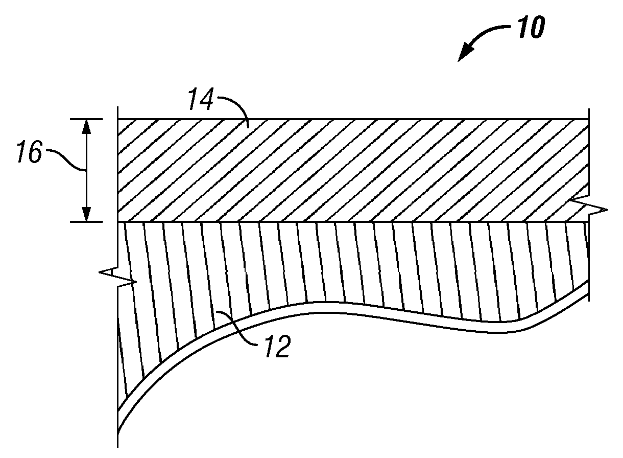
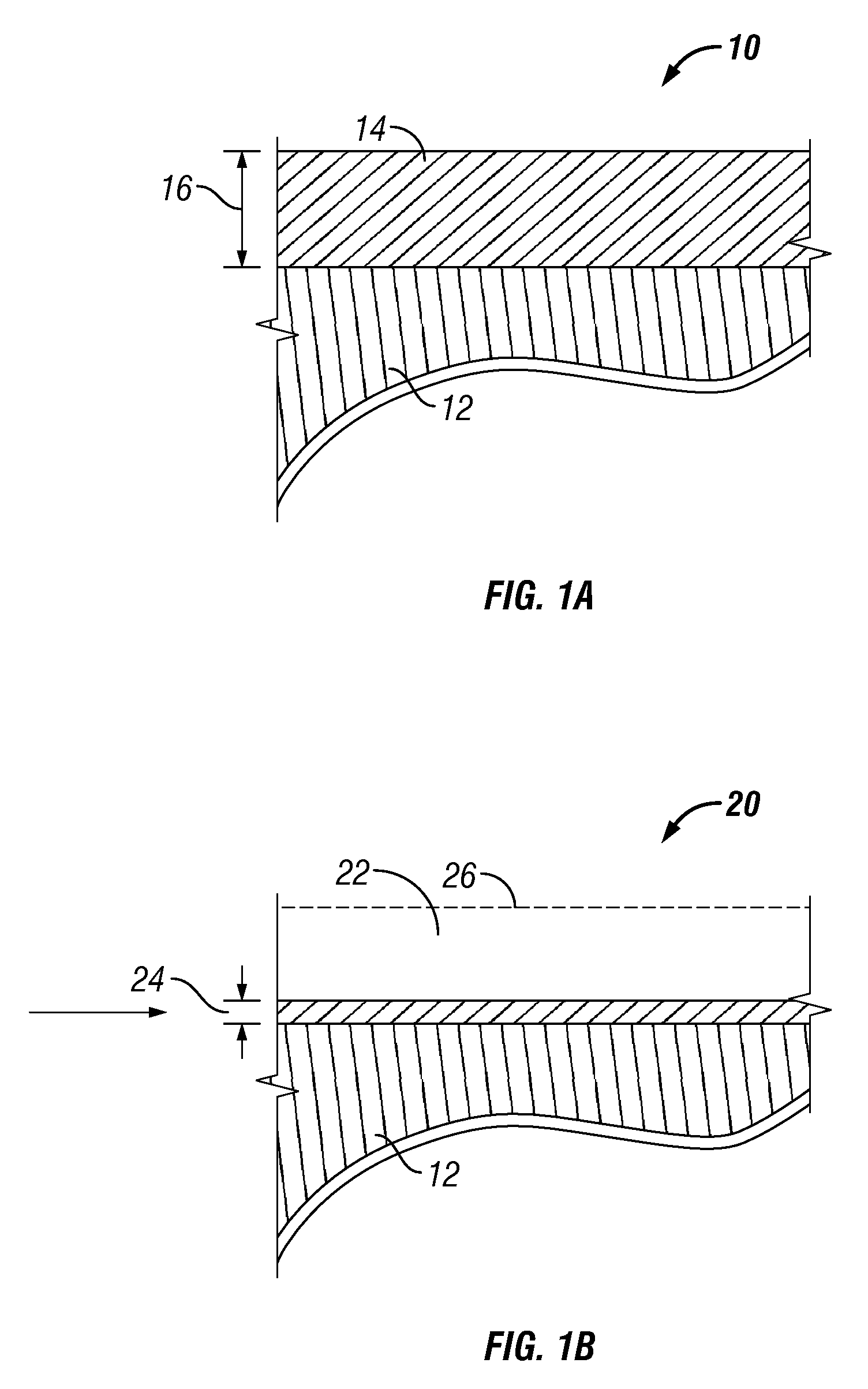
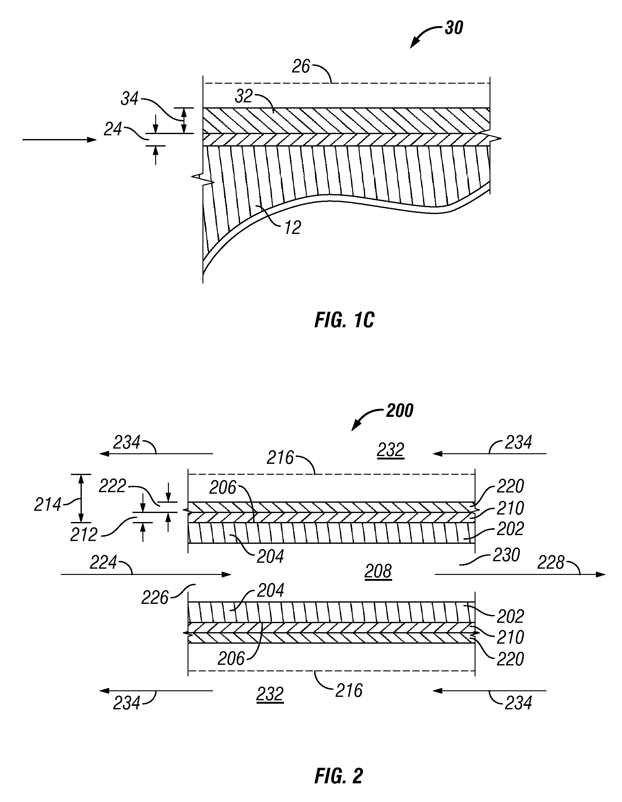
[0055]This Example 1 illustrates the manufacture of a gas separation module by utilizing the inventive method that includes the removal of a substantial portion of the layer of a gas-selective material that has been deposited upon a porous support as a membrane layer of a gas separation module (system). The membrane layer of the gas separation module is formed by deposition of a porous layer of a first material that is abraded or polished followed by the deposition of a second layer of a palladium.

[0056]A gas separation module was manufactured using a method similar to the one described in detail in Example 2 of U.S. Patent Application Publication US 2004 / 0237780, which publication is incorporated herein by reference, followed by the further preparation of the gas separation module using the inventive method. The porous support used in the preparation of the gas separation module was a 2″ OD×6″ length duplex Inconel porous tube obtained from the Mott Corporation. The support tube wa...

example 2

[0059]This Example 2 illustrates the method of reconditioning a gas separation module or membrane system that has been placed in service and, then, subsequently developing a leak in its dense layer.

[0060]A composite gas separation module (module B) was prepared using a 1″ OD×6″ length duplex Inconel support provided by the Mott Corporation.

[0061]Module B was prepared by vacuum deposition of a palladium eggshell catalyst, provided by CRI Catalyst Company, on the duplex support. The eggshell catalyst consists of a material that is spray dried onto alpha alumina particles in such a manner that the material added is only found on the surface of the alpha alumina. A description of the palladium, i.e., noble metal, eggshell catalyst is presented in detail in the copending provisional patent application, filed Nov. 8, 2006 and having application No. 60 / 864,876, which is incorporated herein by reference. The layer of palladium eggshell catalyst was then plated with a layer of palladium unti...

example 3

[0065]This Example 3 illustrates the method of reconditioning or repairing a gas separation module or membrane system that has been damaged during its manufacture so as to cause a leak in the dense layer of the membrane system.

[0066]Module C was made by the same method as described in Example 2, but during its production and after a gas dense membrane layer of 6 microns was formed, the membrane layer of module C was damaged resulting in a leak. Module C was then repaired by removing a substantial portion of the membrane layer by abrasion with successively finer aluminum oxide sandpaper following the grit progression of 1000, 1500, and 2000. The surface of module C was then polished to a mirror-like finish using an ultra-fine abrasive polishing paste comprised of 0.3-micron alpha alumina particles to provide module C with its membrane layer having a reduced membrane thickness below the thickness of membrane layer of the original module C. An overlayer of palladium was then applied to...


PUM

PropertyMeasurementUnit
thicknessaaaaaaaaaa
thicknessaaaaaaaaaa
thicknessaaaaaaaaaa

Abstract

A gas separation membrane system and a method of preparing such gas separation membrane system by providing a porous support upon which is supported a membrane layer comprising a first gas-selective material and having a membrane thickness and removing therefrom a substantial portion of the first gas-selective material from the membrane layer by the use of an ultra-fine abrasive to thereby provide the membrane layer having a reduced membrane thickness. A second gas-selective material is deposited upon the membrane layer having the reduced membrane thickness to provide an overlayer of the second gas-selective material having an overlayer thickness so as to thereby provide the gas separation membrane system having the membrane layer of the reduced membrane thickness and the overlayer of the overlayer thickness.

Description

CROSS-REFERENCE TO RELATED APPLICATIONS[0001]This application claims the benefit of U.S. Provisional Application No. 60 / 890,722 filed Feb. 20, 2007, the entire disclosure of which is hereby incorporated by reference.FIELD OF THE INVENTION[0002]This invention relates to a method of preparing or reconditioning a gas separation membrane system, the gas separation membrane system itself, and the use thereof.BACKGROUND OF THE INVENTION[0003]Composite gas separation modules are commonly used to selectively separate a particular gas from a gas mixture. These composite gas separation modules may be made of a variety of materials, including, for example, polymers and metallic composites. While these composite gas separation modules can provide effective and cost efficient alternatives for the separation of gases at low temperature process conditions, they often are unsuitable for use in high temperature and pressure gas separation processing.[0004]Certain types of gas separation modules are ...

Claims


Application Information

Patent Timeline
Patent Type & Authority Patents(United States)
IPC IPC(8): B01D53/22
CPCB01D53/228B01D67/0086B01D69/12B01D71/022B01J23/44C01B3/503C01B3/505B01D67/0069C01B2203/0495B01D2325/04B01J35/008C01B2203/0405C01B2203/047C01B2203/0475C01B2203/048B01D69/1213
Inventor DEL PAGGIO, ALAN ANTHONYSAUKAITIS, JOHN CHARLES
Owner SHELL OIL CO
Why Eureka
Try Eureka