Method and system for optimizing integrated circuit layout

a technology of integrated circuits and layouts, applied in the field of integrated circuit manufacturing, can solve the problems of systematic yield failure, difficult to capture feature-dependent interactions with precise design rules, waste of valuable resources, etc., and achieve the effect of effectively tuning the circuit performance, reducing the susceptibility of layouts, and reducing the number of defects that can cause damage to circuits

Active Publication Date: 2012-05-08
IYM TECH
View PDF5 Cites 52 Cited by
  • Summary
  • Abstract
  • Description
  • Claims
  • Application Information

AI Technical Summary

Benefits of technology

[0028]In a preferred embodiment relating to reducing the susceptibility of a layout to defect particles, the inventor formulates the local process modification by relating the constraint distances among edges to the critical area such that the number of defects that can cause damage to the circuit is reduced.
[0029]In a preferred embodiment relating to optimizing the circuit performance associated with a layout, the inventor formulates a local modification to the constraints among edges that influence the current-voltage relationship of the amplification devices, especially those edges that form the structure of the devices. These edges directly influence the current-voltage characteristics of the devices and their related electrical properties. Because the current-voltage properties of t...

Problems solved by technology

Failure to capture the absolute worst case in all chips would lead to systematic yield failure.
For this reason, the feature dependent interactions are difficult to capture with precise design rules.
The drawback of this approach is at least two fold: firstly, by using the worst possible situation as the rule, it clearly wastes valuable chip area, and secondly, finding the worst case feature combination in chips of all kinds, including those that have not been designed at the time of design rule formulat...

Method used


Image

  • Method and system for optimizing integrated circuit layout
  • Method and system for optimizing integrated circuit layout
  • Method and system for optimizing integrated circuit layout

Examples


Embodiment Construction

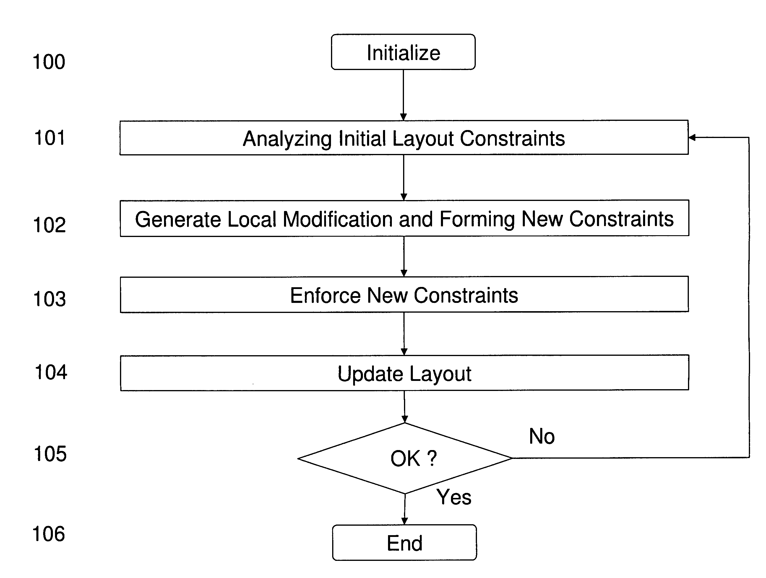
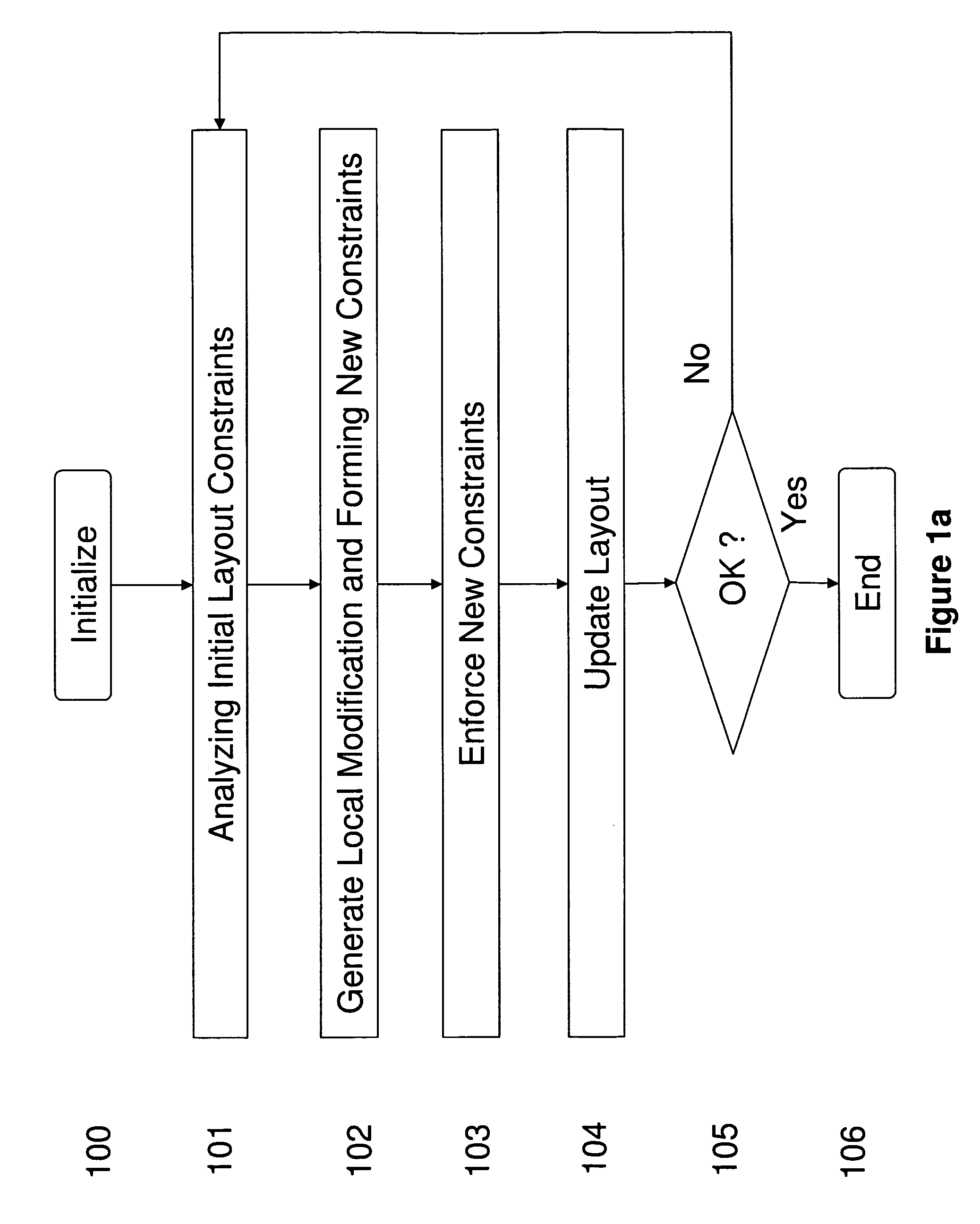
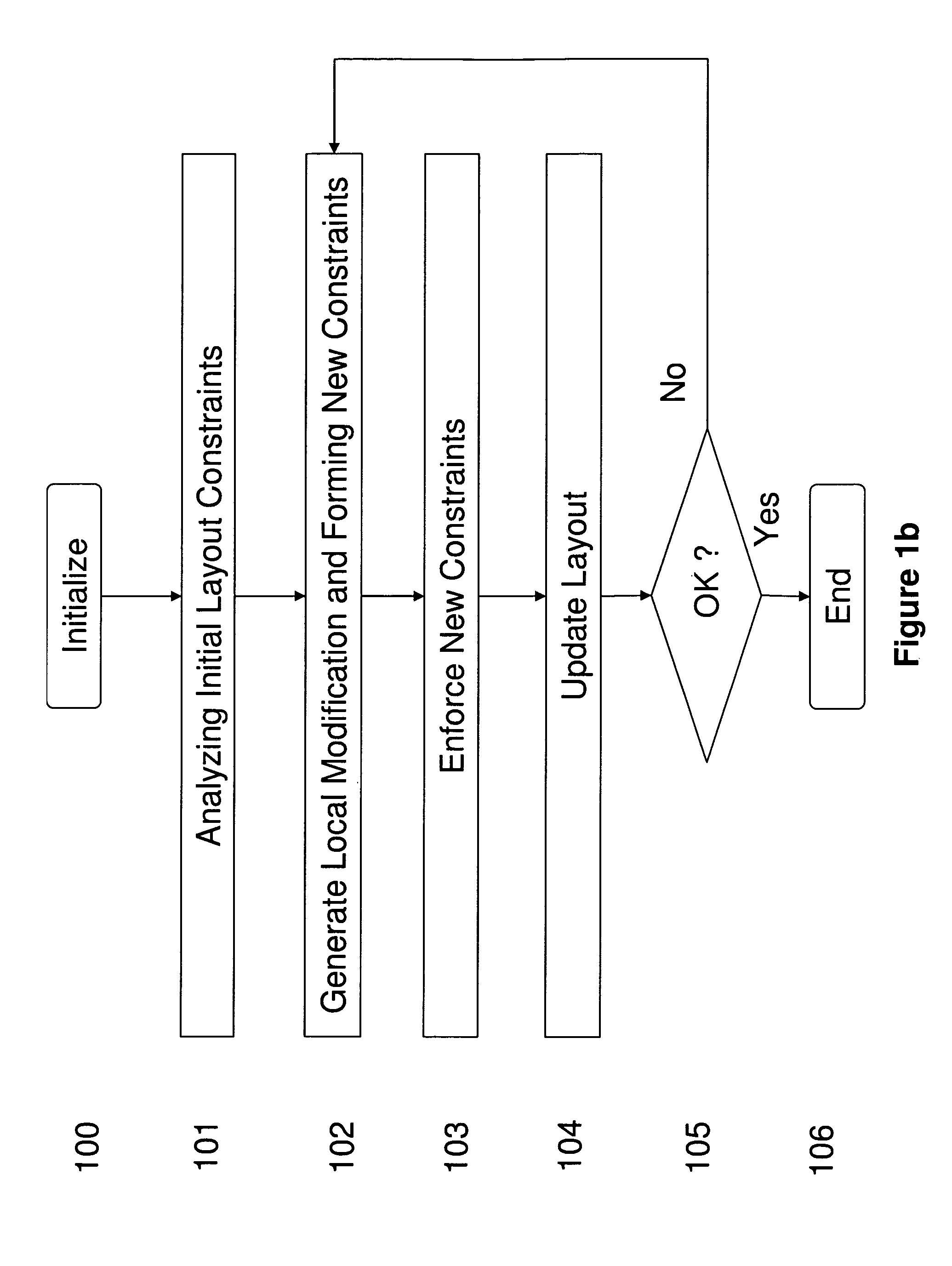
[0048]Some preferred embodiments of the present invention will be described in detail with reference to the related drawings of FIGS. 1-5. Additional embodiments, features and / or advantages of the invention will become apparent from the ensuing description or may be learned by the practice of the invention.

[0049]The methods and apparatus described here are with respect to integrated circuit manufacturing; however, the techniques described here can be applied to manufacturing or design of any device. Examples of these include integrated optical devices, microelectromechanical systems (MEMS), gene chips, micromachines, disk drive heads, etc.

[0050]The following description includes the best mode presently contemplated for carrying out the invention. This description is not to be taken in a limiting sense, but is made merely for describing the general principles of the invention.

[0051]The present invention is directed to method and system for improving the manufacturing yield, circuit p...


PUM


Abstract

We disclose a method for optimizing integrated circuit layout which comprises analyzing constraint relationship among objects in an initial layout; constructing local modifications to the constraint relationship; forming new constraint relationships by combining initial constraint relationships with their local modifications; and producing a new layout by implementing the new constraint relationships. Local modification to constraints provides a framework for bringing detailed local information into the design process in a highly automated manner, which can be applied to a wide range of situations. We disclose preferred embodiments on improving lithography printability, reducing defect susceptibility, and improving circuit performance such as reducing layout variability and leakage.

Description

CROSS REFERENCE TO RELATED APPLICATIONS[0001]This application is a continuation-in-part of and claims priority to U.S. patent application Ser. No. 10 / 907,814 filed on Apr. 15, 2005.[0002]This application is also related to copending application by Qi-De Qian entitled “Anisotropic Layout for Integrated Circuits” filed on even date herewith.[0003]Each application referenced above is incorporated herein by reference in its entirety.FIELD OF THE INVENTION[0004]The present invention relates generally to integrated-circuit manufacturing and more particularly to methods and system for generating and optimizing its layout artwork.PRIOR ART[0005]An integrated circuit (“IC”) is a semiconductor device that includes many electronic components (e.g., transistors, diodes, etc.). These components are interconnected to form larger scale circuit building blocks (e.g., gates, cells, memory units, arithmetic units, controllers, decoders, etc.) on the IC. These circuit building blocks are the building ...

Claims


Application Information

Patent Timeline
IPC IPC(8): G06F17/50
CPCG06F17/5068G06F30/39
Inventor QIAN, QI-DE
Owner IYM TECH
Why Eureka
Try Eureka