Method and apparatus to treat well stimulation fluids in-situ

a well stimulation and fluid treatment technology, applied in the field of subterranean fluid treatment, can solve the problems of increased stimulation treatment cost, increased injection cost, and damage to the subterranean reservoir by friction reducers, so as to reduce the damage of stimulation, improve the environmental quality of flow back, and improve the control of viscosity effect

Inactive Publication Date: 2012-06-12
SMITH DAVID RANDOLPH
View PDF17 Cites 7 Cited by
  • Summary
  • Abstract
  • Description
  • Claims
  • Application Information

AI Technical Summary

Benefits of technology

[0009]The present invention is directed to a new method and apparatus to treat well stimulation fluids in-situ thereby improving the control on viscosity effects of said fluids due to cross linkers, gels, and polyacrylamides, thereby reducing the damage that stimulation fluids and chemical have on reservoir productivity, controlling dynamically during a stimulation process the injection profile of fluids into the reservoir, and improving the environmental quality of the flow back of said stimulation treatment fluids when they are flowed back to the surface of the earth or sea. The present method also aids in the recovery of naturally-occurring subterranean reservoir fluids such as oil and natural gas.

Problems solved by technology

Without the friction reduction chemicals, the amount of hydraulic horsepower required to inject fluids into the well becomes higher requiring more surface pumping power and equipment thereby, drastically increasing the cost of a stimulation treatment.
Hence, one often faces the dilemma whereby if one performs a stimulation or hydraulic fracture treatment without friction reducer chemicals in the fluid, the cost of injection is much higher due to energy costs, but if one opts to mix at surface friction reduction chemicals in the stimulation or hydraulic fracture fluid to reduce horsepower requirements, damage to the subterranean reservoir from said friction reducers occurs.
Furthermore, as fluids are flowed back to the surface after the injection process these flowed-back fluids containing chemicals used during the injection cause environmental damage to the surface environment and to well tubular that transduce them to surface.
This damage can be scale deposits in the well casing, corrosion in the well casing, and detrimental effects on surface flow back equipment.
Often to reduce the surface damage to the environment, the fluids must be treated with additional chemicals at the surface or specially disposed of at surface, further increasing the cost to using fluids and chemicals on injection jobs like said stimulation and fracture treatments.
Moreover, there are other problems with these injected fluids when they are produced back from the wells.
There are many detrimental issues with this produced-back stimulation fluid, mostly owing to the fact that the produced-back fluids are complex mixtures of a number of chemical materials and are further contaminated from the subterranean environment after the injection process and often contain bacteria, salts, scales, gases, enzymes, viruses, and other materials that are not suitable for surface handling, disposal or re-injection into wells during a subsequent stimulation or hydraulic fracture process.
These compositions injected at surface often reduce the hydraulic friction pressure developed between the well tubular and the fluids being pumped down the well hence the required hydraulic horsepower for the injection, but the result is that the chemicals mixed at surface often cause residual damage to the reservoir.
The damage often diminishes subsequent production of hydrocarbons from the reservoir.
This damage results in part, because these chemicals, usually large polymer chains, have long molecular structures and significant surface tension, making their recovery from the reservoir rock during stimulation flow back difficult.
Furthermore, the stimulation fluids having the chemicals mixed into them at surface, and having a certain amount of oxygen entrained from the surface mixing process, react in-situ in the reservoir enhancing bacterial growth and resulting in unwanted gas, bacterial growth, fluid pH modifications and scale.
These surface-mixed chemicals and fluids combine in the reservoir with heat and oxygen from the surface to accelerate bacteria growth in the stimulation fluid leading to the detrimental generation of in-situ gases, bacteria, fluid pH modifications, and scale, that combine with these reservoir fluids and polymers to cause corrosion and scale precipitation to occur in the reservoir and well.
Furthermore, these chemicals and fluids, when flowed back to the well surface, result in toxic surface fluids that are note easily and inexpensively disposed.
Finally, the flowed back stimulation fluids with the injected chemicals and fluids now representing bacterial loaded fluids are unsatisfactory to re-inject during subsequent well stimulation treatments.
If crosslinking occurs in the fluid too quickly, then there will be excessive viscosity developed in the fluid being transported through the well tubulars causing increased fluid hydraulic friction between the fluid and the well conduit too early in the transport time of the fluid in the well conduit, thereby causing the surface injection pressure to become excessively high and resulting in the need for more surface hydraulic horsepower to inject the fluids.
This timing of cross linking is difficult to achieve in practice as it is a function of the well depth, well temperature, fluid pH, fluid temperature, gel and crosslinker mixing proportions achieved on surface in a dynamic “on the fly” mixing process, and the injection rate of the fluids.
Currently, the crosslinking effect cannot be quickly controlled and changed from surface as the fluids in the well have already been mixed at surface and because the reservoir being injected to can be miles away in depth from the surface, hence the transient time between the time at which the crosslinked fluid is injected at surface and the time at which it arrives at the perforations in the reservoir is typically longer than is desirable.
However, when surface mixing crosslinkers or other fluid viscosity modifiers, it very difficult to rapidly change the friction pressure of the fluids by the effect of crosslinking of the gelled fluid.
This is due to a number of reasons, including the significant distances that the fluid being injected must travel from the surface to the reservoir and resulting long transit time.
A still further problem presented by current oil and gas industry methods of crosslinking and viscosity-modifying fluids is that is in many wells, fluids are injected in large zones separated by many thousands of feet.

Method used


Image

  • Method and apparatus to treat well stimulation fluids in-situ
  • Method and apparatus to treat well stimulation fluids in-situ
  • Method and apparatus to treat well stimulation fluids in-situ

Examples


Embodiment Construction

[0030]As used herein, “a” or “an” means one or more. Unless otherwise indicated, the singular contains the plural and the plural contains the singular.

[0031]As used herein, “surface” refers to locations at or above the surface.

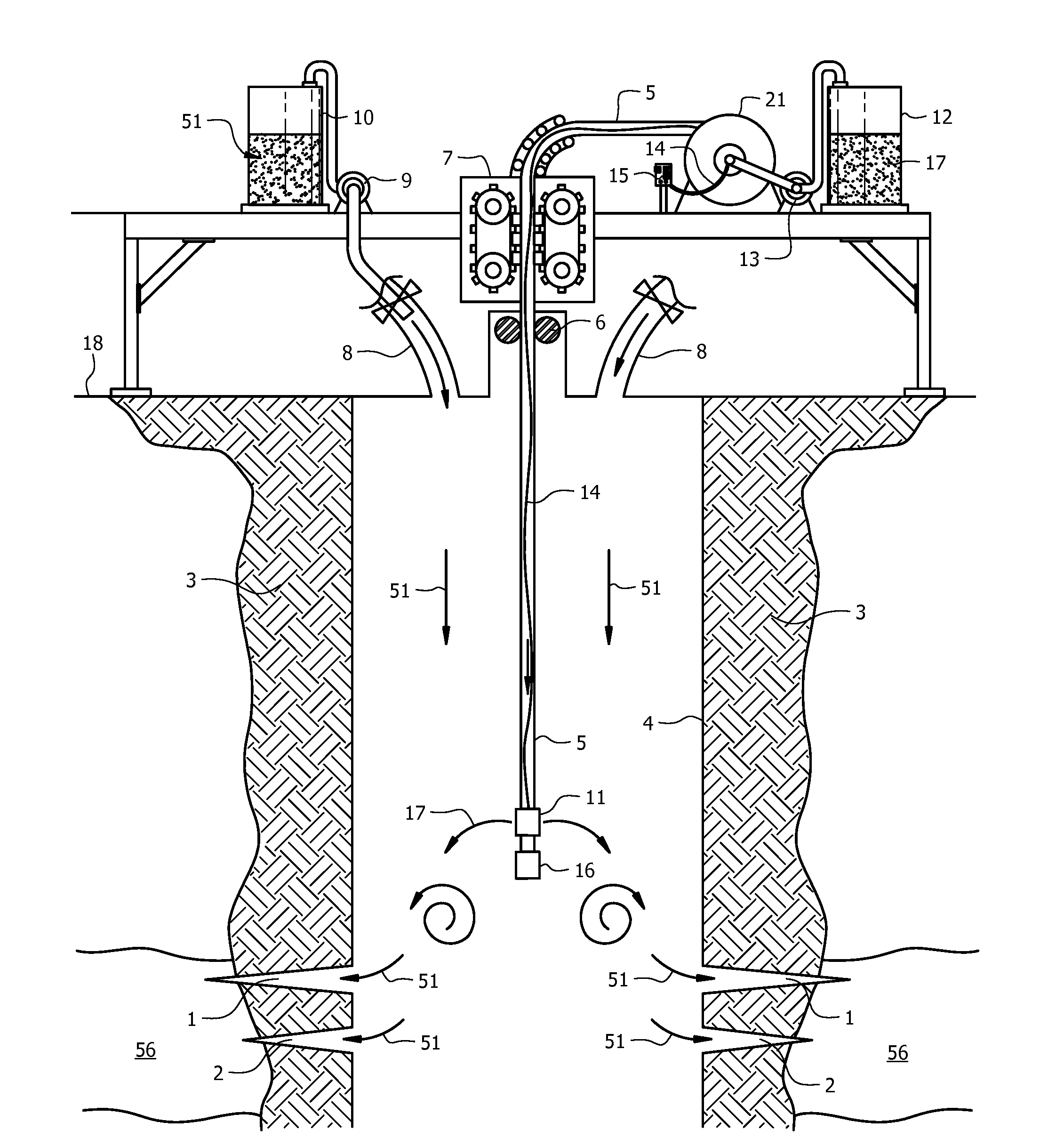
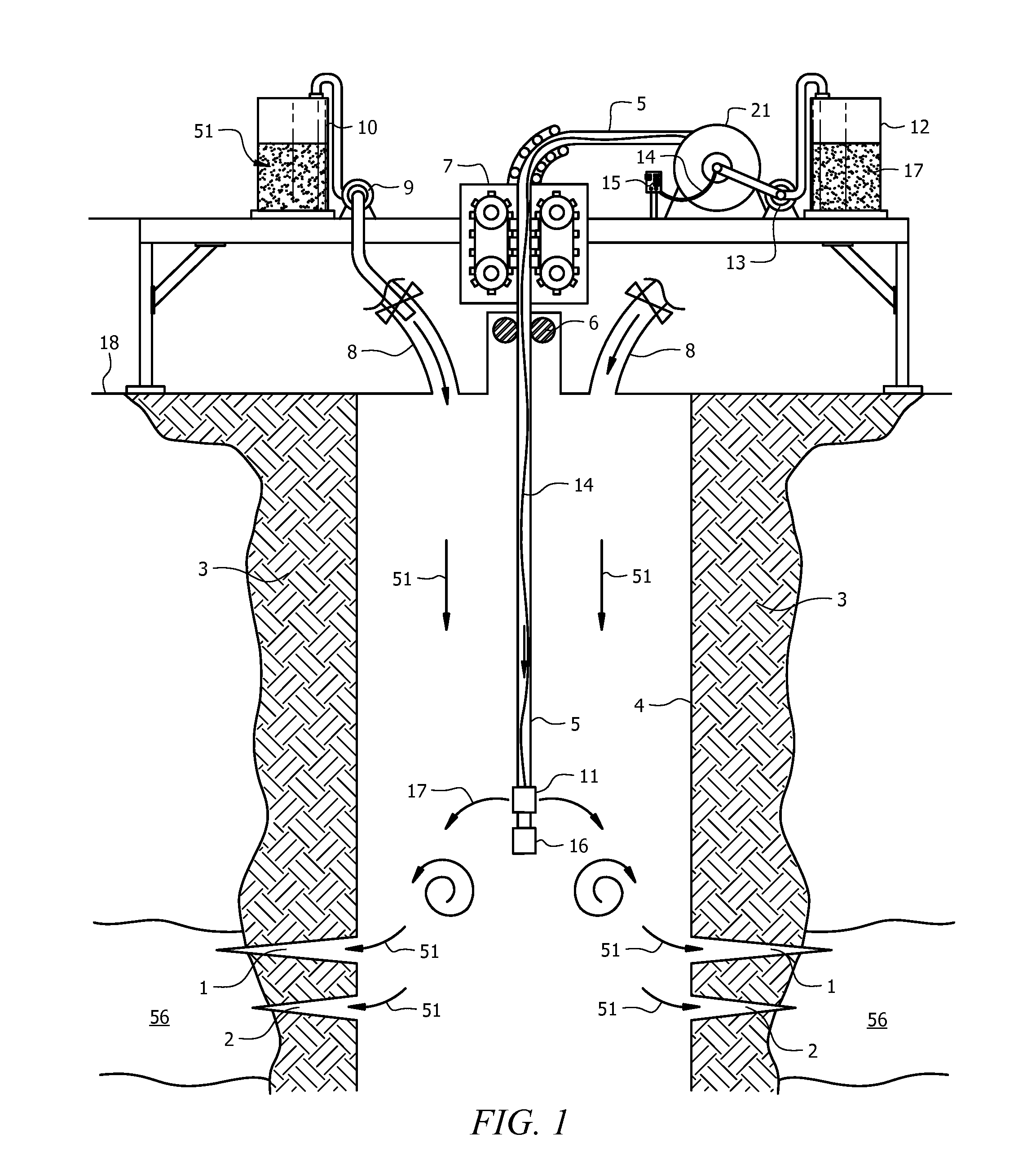
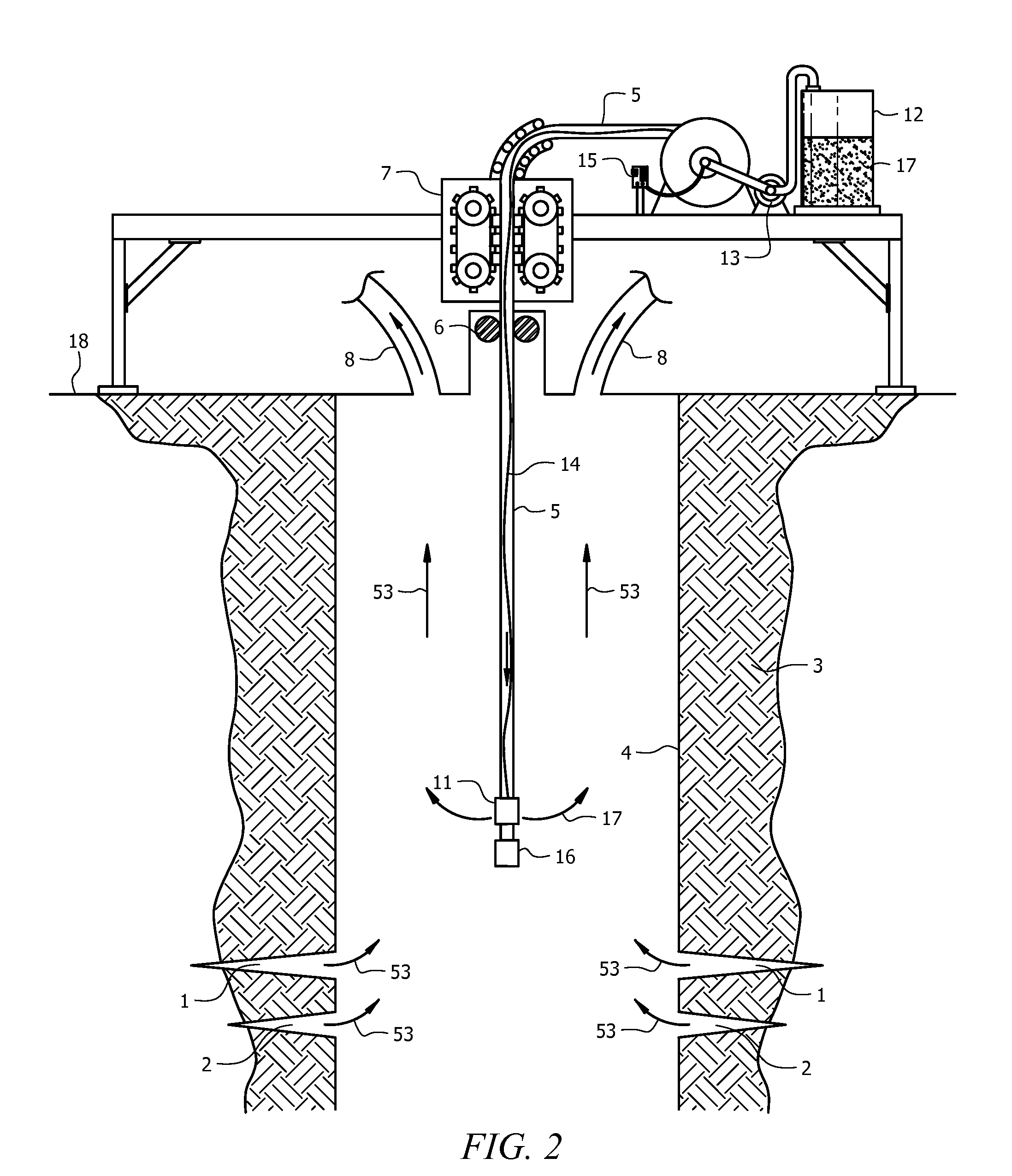
[0032]Attention is first directed to FIG. 1 wherein the preferred embodiment is shown. In the preferred embodiment of this invention, there is a well construction method method where a first conduit 4 commonly known to those familiar with the art of well construction as casing is deployed into the earth 18 through the well bore 3. Casing 4 is grouted into a well bore 3 in the earth 18 generally referred to as a well bore 3. A second conduit, shown in FIG. 1 as conduit 5, may be deployed into the well bore 3 through the casing 4. Conduit 5 may be a continuous length of tubing, referred to as coiled tubing, and is lowered and extracted from the well through an elastomeric sealing device 6 separating the well pressure environment from the surface environment. It ...


PUM

PropertyMeasurementUnit
depthaaaaaaaaaa
viscosityaaaaaaaaaa
lengthaaaaaaaaaa

Abstract

A method and apparatus for the management of injection and production of well fluids in a subterranean well is described to optimize the use of stimulation fluids to enhance their compatibility with subterranean reservoirs and the surface environment and thereby reducing the damage said fluids induce in subterranean reservoirs and upon flow back to the surface reduce their damage to the environment is described. More specifically, this method is directed to the subterranean treatment of injection fluids.

Description

CROSS-REFERENCE TO RELATED APPLICATIONS[0001]This application claims priority to U.S. provisional application Ser. No. 61 / 028,729, filed on Feb. 14, 2008.TECHNICAL FIELD[0002]The present invention is directed to a subterranean mixing method and apparatus to treat well fluids to enhance their compatibility with subterranean reservoirs reducing the damage said fluids induce in subterranean reservoirs and to improve the environmental compatibility of well fluids produced to the surface. More specifically, this invention is directed to the subterranean treatment of fluids.BACKGROUND OF THE INVENTION[0003]When a fluid, such as oil and natural gas, is being produced from a subterranean reservoir through a wellbore, the ability of the reservoir to produce hydrocarbons and other fluids is often enhanced by processes that inject fluids and solids from surface into the well reservoir. These fluids are known to those of skill in the art of oil and gas production as stimulation fluids or hydrau...

Claims


Application Information

Patent Timeline
Patent Type & Authority Patents(United States)
IPC IPC(8): E21B43/22C09K8/62E21B47/01
CPCC09K8/685E21B43/16E21B43/162C09K2208/34Y10S507/935
Inventor SMITH, DAVID RANDOLPH
Owner SMITH DAVID RANDOLPH
Why Eureka
Try Eureka