Power generation process with partial recycle of carbon dioxide

a technology of carbon dioxide and power generation process, which is applied in the direction of separation process, machine/engine, lighting and heating apparatus, etc., can solve the problems of complex separation of carbon dioxide from this very large dilute stream, huge amount of flue gas generated by power plants, etc., and achieve the effect of reducing the environmental impact of discharging stream and capturing more efficiently

Active Publication Date: 2012-07-17
MEMBRANE TECH & RES
View PDF15 Cites 113 Cited by
  • Summary
  • Abstract
  • Description
  • Claims
  • Application Information

AI Technical Summary

Benefits of technology

[0020]The major components of combustion exhaust gases are normally nitrogen, carbon dioxide, and water vapor. Other components that may be present, typically only in small amounts, include oxygen, hydrogen, SOx, NOx, and unburnt hydrocarbons. Syngas may also contain heavy metals, such as mercury. The carbon dioxide concentration in the flue gas can be up to about 20 volume %, but in most power plants, the exhaust gas contains between 4-8% carbon dioxide. Separating the carbon dioxide from this very large dilute stream is complex. The processes described herein produce more concentrated and smaller exhaust streams. Downstream separation of concentrated carbon dioxide for sequestration or other uses is then much more economical.
[0044]Another objective of the invention is to minimize the amount of carbon dioxide in the residue stream from the sweep-based membrane separation step, which is often released to the environment. As such, the residue stream preferably comprises less than 5 volume % carbon dioxide; more preferably, less than 3 volume % carbon dioxide; and, most preferably, less than 2 volume % carbon dioxide. Most preferably, at least 80% of the carbon dioxide generated in the power generation process is recovered by the process of the invention. The substantial reduction of the carbon dioxide content in the raw exhaust greatly reduces the environmental impact of discharging the stream.

Problems solved by technology

Power plants generate enormous amounts of flue gas.
Separating the carbon dioxide from this very large dilute stream is complex.

Method used


Image

  • Power generation process with partial recycle of carbon dioxide
  • Power generation process with partial recycle of carbon dioxide
  • Power generation process with partial recycle of carbon dioxide

Examples


example 1

Bases of Calculations for Other Examples

[0220](a) Membrane permeation experiments: The following calculations were performed using a composite membrane having a polyether-based selective layer with the properties shown in Table 1.

[0221]

TABLE 1GasPermeance (gpu)*CO2 / Gas SelectivityMethane9011Nitrogen3033Oxygen6017Water5,000** —Carbon dioxide1,000  —*Gas permeation unit; 1 gpu = 1 × 10⁻⁶ cm3(STP) / cm2 · s · cmHg**Estimated, not measured

[0222](b) Calculation methodology: All calculations were performed using a modeling program, ChemCad 5.6 (ChemStations, Inc., Houston, Tex.), containing code for the membrane operation developed by MTR's engineering group. For the calculations, all compressors and vacuum pumps were assumed to be 75% efficient. In each case, the modeling calculation was performed to achieve the following results:[0223]a concentration of at least about 15 volume % oxygen in the oxygen-containing gas feed to the combustor;[0224]a concentration of at least about 2 volume % o...

example 2

Combustion Process with Partial Flue Gas Recycle and No Sweep-Based Membrane Separation (not in Accordance with the Invention)

[0233]A computer calculation was performed to determine the chemical composition of exhaust gas from a natural gas combustion process, with partial flue gas recycle and no membrane sweep. The process differed from the base-case calculation of Example 1 in that the intake of air was reduced to about half that of Example 1 (in other words, the minimum amount to provide for complete combustion), and the remainder of the gas required for temperature and flow control in the combustor was assumed to be provided by recirculating a portion of the combustion exhaust gas to the combustor inlet, as is commonly done. FIG. 4 is a schematic drawing of a flow scheme for such a combustion process.

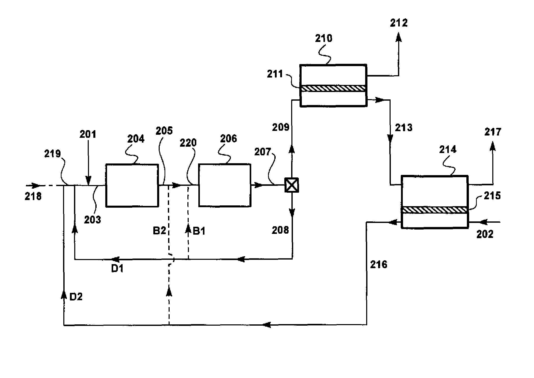
[0234]Referring to FIG. 4, natural gas stream 401 and compressed oxygen-containing gas stream 409 are introduced as feed stream 403 into combustion step or zone 404. Stream 409 is m...

example 3

Combustion Process with Membrane Sweep and No Flue Gas Recycle (not in Accordance with the Invention)

[0240]A computer calculation was performed to determine the chemical composition of exhaust gas from a natural gas combustion process, with membrane sweep, but no flue gas recycle. FIG. 5 is a schematic drawing of a flow scheme for such a combustion process.

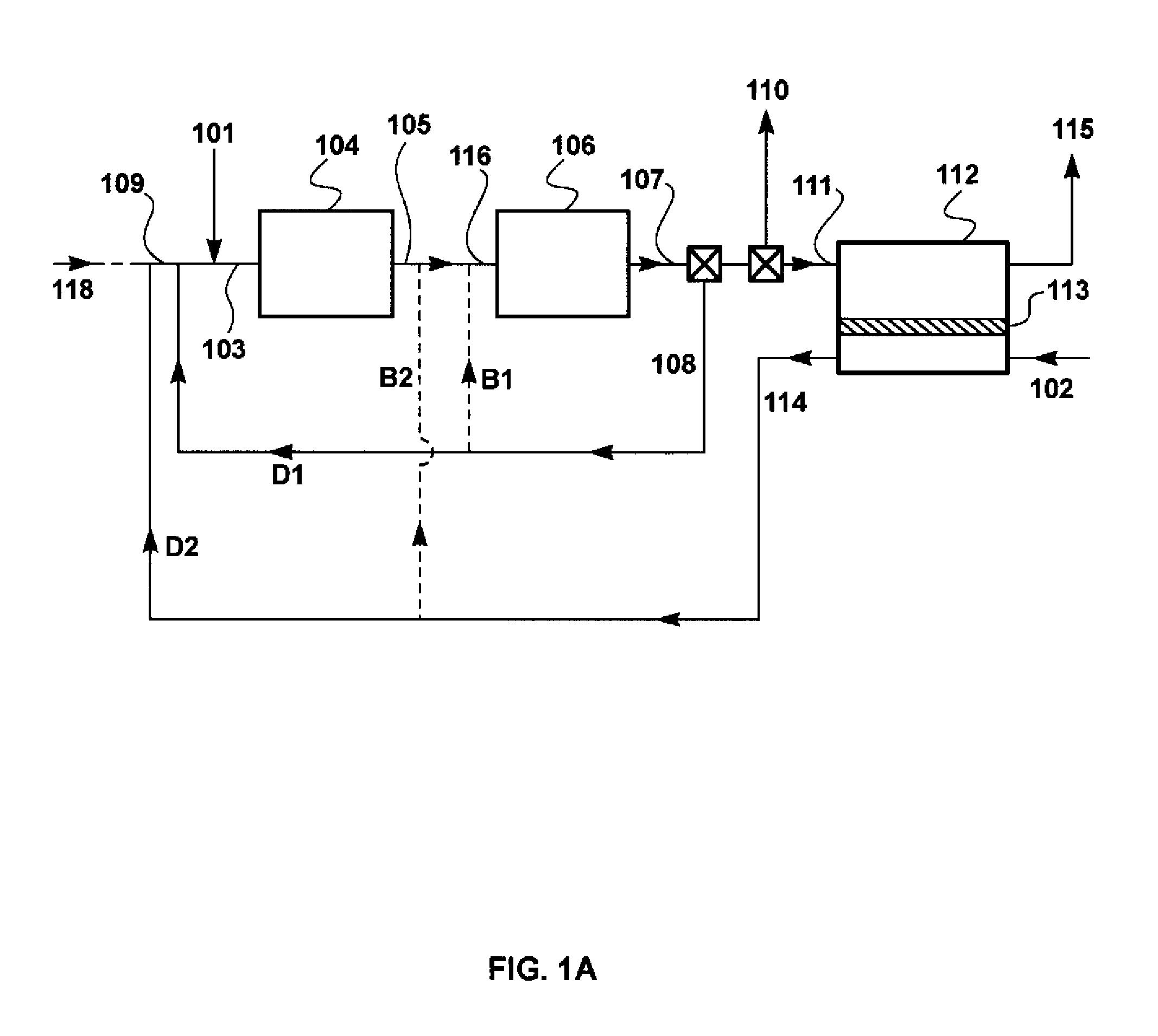
[0241]Referring to FIG. 5, natural gas stream 501 and compressed combined sweep / permeate stream 512 are introduced as feed stream 503 into combustion step or zone 504. The mass flow rate of the natural gas stream 501 was 71.6 kg / h.

[0242]Combustion exhaust stream 505 is withdrawn, then routed through gas turbine 506 and a condenser (not shown) to knock water out of the stream. The dehydrated turbine exhaust stream 507 is then routed through a splitter, where it is divided into a first portion 508 and a second portion 509. In this example, the first portion 508 and the second portion 509 were in a ratio of 1:5.6 (flow to carbon diox...


PUM


Abstract

Disclosed herein is a power generation process in which a portion of the carbon dioxide generated by gaseous fuel combustion is recycled back to the power generation process, either pre-combustion, post-combustion, or both. The power generation process of the invention may be a combined cycle process or a traditional power generation process. The process utilizes sweep-based membrane separation.

Description

RELATED APPLICATIONS[0001]This application claims the benefit of PCT Application No. PCT / US10 / 02480, filed Sep. 13, 2010, and U.S. application Ser. No. 13 / 122,136, filed Mar. 31, 2011, the disclosures of which are hereby incorporated herein by reference in their entireties.FIELD OF THE INVENTION[0002]The invention pertains to a power generation process in which a portion of the carbon dioxide generated by gaseous fuel combustion is recycled back to the power generation process, either pre-combustion, post-combustion, or both. The power generation process may be a combined cycle process or a traditional power generation process.BACKGROUND OF THE INVENTION[0003]In a traditional power generation process, a gaseous fuel (such as natural gas or syngas) is combusted in the presence of oxygen, producing a stream of hot, high-pressure gas. This hot, high-pressure gas is then used to drive a gas turbine, which in turn drives a generator, producing electrical energy. The exhaust gas from the ...

Claims


Application Information

Patent Timeline
Patent Type & Authority Patents(United States)
IPC IPC(8): F02C1/00F02C3/00F02G1/00F02G3/00
CPCB01D53/22B01D53/62F02C3/34F23C9/00B01D2256/22B01D2257/102B01D2257/104B01D2257/504B01D2258/0283F23L2900/07001Y02C10/04Y02C10/10Y02E20/16Y02E20/322Y02C20/40Y02E20/32
Inventor WIJMANS, JOHANNES G.MERKEL, TIMOTHY C.BAKER, RICHARD W.WEI, XIAOTONG
Owner MEMBRANE TECH & RES
Why Eureka
Try Eureka