Flow control in microfluidic systems

a microfluidic system and flow control technology, applied in the field of microfluidic systems, can solve the problems of adding a level of cost and sophistication, and achieve the effect of reducing the volumetric flow ra

Active Publication Date: 2012-07-17
OPKO DIAGNOSTICS
View PDF116 Cites 56 Cited by
  • Summary
  • Abstract
  • Description
  • Claims
  • Application Information

AI Technical Summary

Benefits of technology

[0008]In another embodiment, a method of operating a microfluidic system comprises applying a pressure drop across an inlet and an outlet of a microfluidic system, while carrying out the following steps: flowing a first fluid from a first channel portion to a second channel portion positioned between the inlet and the outlet of the microfluidic system, wherein a fluid path defined by the first channel portion has a larger cross-sectional area than a cross-sectional area of a fluid path defined by the second channel portion; without stopping the first fluid, causing a volumetric flow rate of the first fluid to decrease by a factor of at least 50 in the microfluidic system as a result of the first fluid flowing from the first channel portion to the second channel portion; and preventing any of the first fluid from exiting the microfluidic system via the outlet during operation of the microfluidic system as a result of the decrease in volumetric flow rate of the first fluid.

Problems solved by technology

While various microfluidic methods and devices, such as microfluidic assays, can provide inexpensive, sensitive and accurate analytical platforms, fluid manipulations—such as sample introduction, introduction of reagents, storage of reagents, separation of fluids, modulation of flow rate, collection of waste, extraction of fluids for off-chip analysis, and transfer of fluids from one chip to the next—can add a level of cost and sophistication.

Method used


Image

  • Flow control in microfluidic systems
  • Flow control in microfluidic systems
  • Flow control in microfluidic systems

Examples


example 1

Fabrication of Microfluidic Channels

[0134]A method for fabricating a microfluidic channel system is described.

[0135]Channel systems, such as the ones shown in FIGS. 1-8, were designed with a computer-aided design (CAD) program. The microfluidic devices were formed in poly(dimethylsiloxane) Sylgard 184 (PDMS, Dow Corning, Ellsworth, Germantown, Wis.) by rapid prototyping using masters made in SU8 photoresist (MicroChem, Newton, Mass.). The masters were produced on a silicon wafer and were used to replicate the negative pattern in PDMS. The masters contained two levels of SU8, one level with a thickness (height) of ˜70 μm defining the channels in the immunoassay area, and a second thickness (height) of ˜360 μm defining the reagent storage and waste areas. Another master was designed with channel having a thickness (height) of 33 μm. The masters were silanized with (tridecafluoro-1,1,2,2-tetrahydrooctyl)trichlorosilane (ABC-R, Germany). PDMS was mixed according to the manufacturer's in...

example 2

Regulating Flow Rate Using Differential Viscosity of Fluids and a Flow Constriction Positioned Upstream of an Analysis Region

[0137]This example describes a method for regulating the flow rate in a microchannel using a flow constriction region positioned upstream of an analysis region and fluids of different viscosities.

[0138]The microchannels produced in PDMS or Polystyrene (see Example 1) were sealed against a plate of polystyrene (NUNC Omnitray, VWR, West Chester, Pa.) in the case of PDMS, or a biocompatible adhesive (in the case of polystyrene substrates). For the latter, the polystyrene substrate was drilled to obtain access holes prior to application of the cover. In a different approach, the holes were formed in the thermoplastic during the injection molding process by using pillars inside the cavity of the injection molding machine.

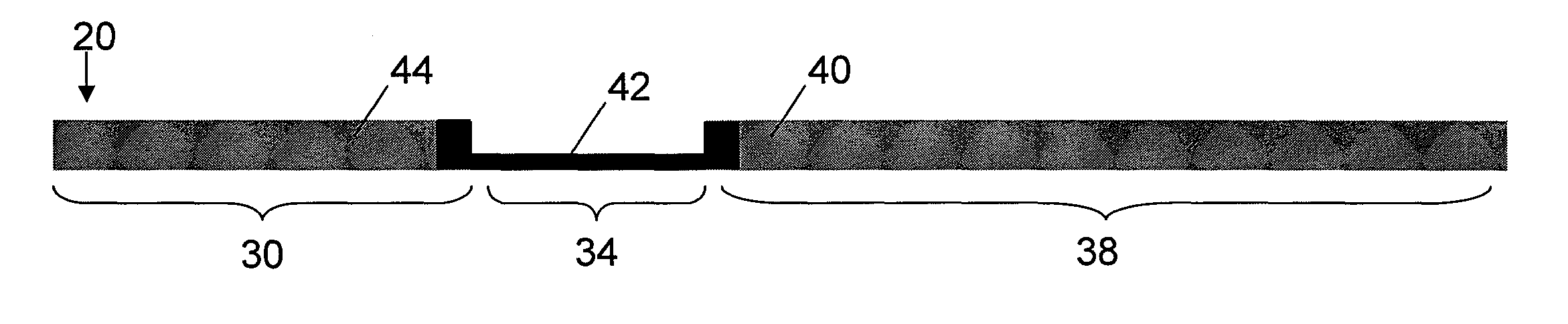
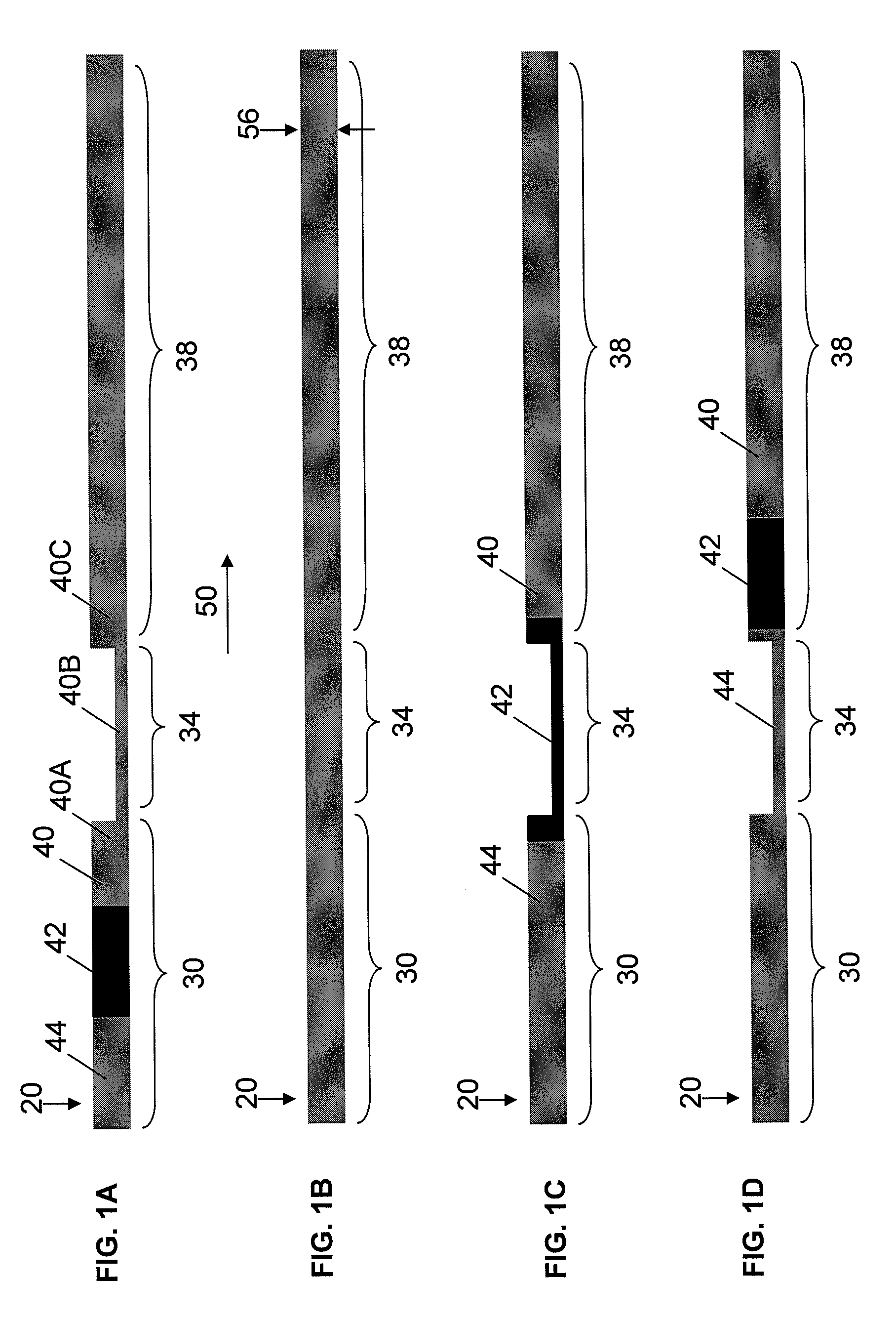
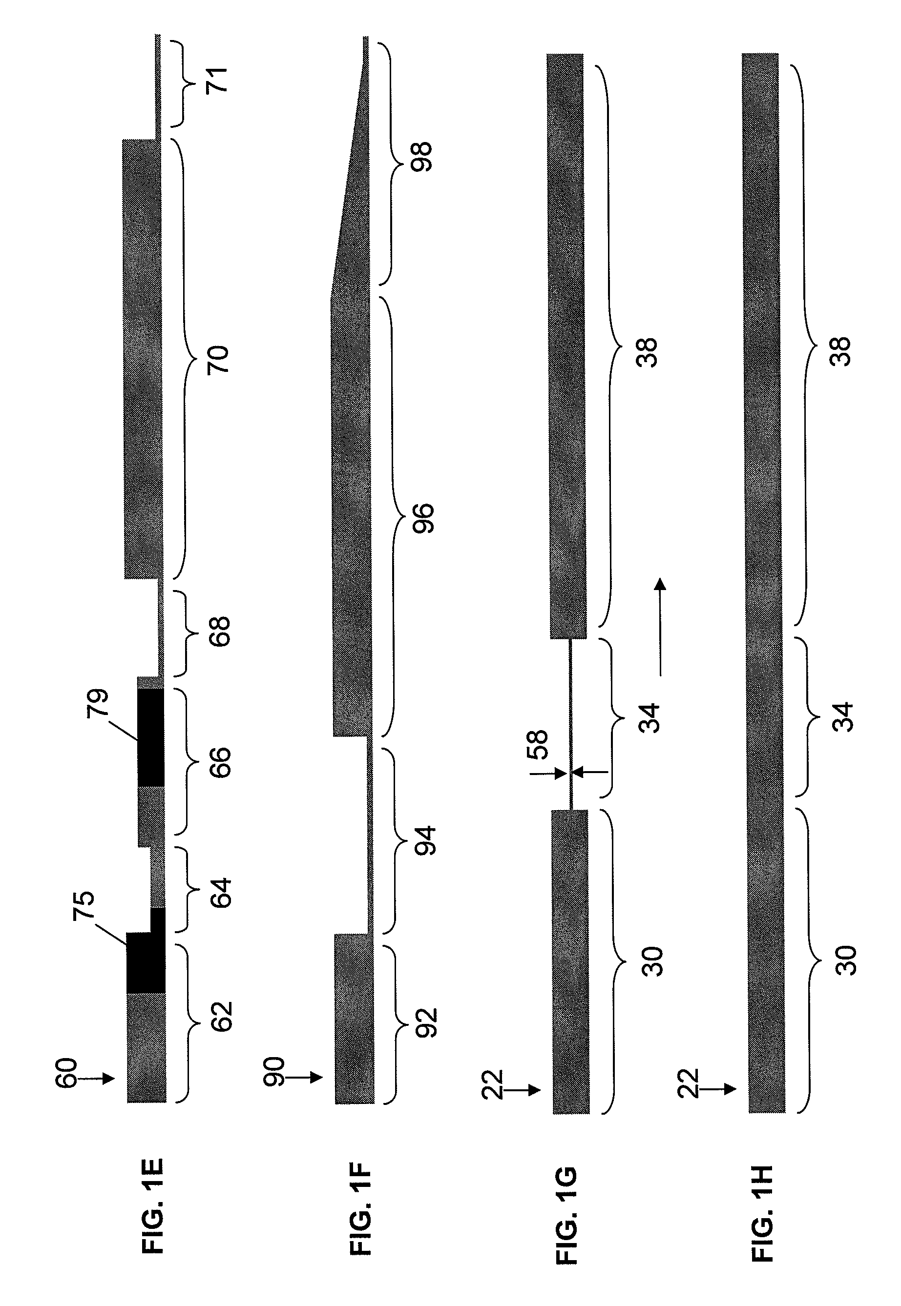
[0139]A first channel portion 30 and a third channel portion 38 (e.g., as shown in FIG. 1) were 500 μm wide and 376 μm deep; second channel portio...

example 3

Regulating Flow Rate Using Differential Viscosity of Fluids and a Flow Constriction Positioned Near an Outlet of a Microchannel System

[0146]This example describes a method for regulating the flow rate in a channel using a flow constriction positioned downstream of an analysis region near an outlet of the microchannel system.

[0147]A microfluidic device having four sections, as shown in FIG. 6A, was formed using the method described in Example 1. The first section included a channel 78 having a width of 120 μm and a depth of 50 μm connecting the inlet of the device to a second section, a liquid containment region 80. Some areas of channel 7 were modified with biochemical probes to perform a heterogeneous assay (e.g., an immunoassay). The liquid containment region (33 mm in diameter, 370 μm deep) contained an absorbent material (polyester / cellulose wiper, VWR). Downstream of the chamber was a third section, a flow constriction region 82 in the form of a narrow channel (50 μm wide, 33 μ...


PUM

PropertyMeasurementUnit
lengthaaaaaaaaaa
widthaaaaaaaaaa
widthaaaaaaaaaa

Abstract

Microfluidic systems and methods including those that provide control of fluid flow are provided. Such systems and methods can be used, for example, to control pressure-driven flow based on the influence of channel geometry and the viscosity of one or more fluids inside the system. One method includes flowing a plug of a low viscosity fluid and a plug of a high viscosity fluid in a channel including a flow constriction region and a non-constriction region. In one embodiment, the low viscosity fluid flows at a first flow rate in the channel and the flow rate is not substantially affected by the flow constriction region. When the high viscosity fluid flows from the non-constriction region to the flow constriction region, the flow rates of the fluids decrease substantially, since the flow rates, in some systems, are influenced by the highest viscosity fluid flowing in the smallest cross-sectional area of the system (e.g., the flow constriction region). This causes the fluids to flow at the same flow rate at which the high viscosity fluid flows in the flow constriction region. Accordingly, by designing microfluidic systems with flow constriction regions positioned at particular locations and by choosing appropriate viscosities of fluids, a fluid can be made to speed up or slow down at different locations within the system without the use of valves and / or without external control.

Description

RELATED APPLICATIONS[0001]This application claims the benefit of U.S. Provisional Patent Application Ser. No. 61 / 047,923, filed Apr. 25, 2008, entitled “FLOW CONTROL IN MICROFLUIDIC SYSTEMS,” by Linder, et al., which is incorporated herein by reference in its entirety for all purposes.FIELD OF INVENTION[0002]The present invention relates generally to microfluidic systems, and more specifically, to microfluidic systems and methods that provide control of fluid flow.BACKGROUND[0003]The manipulation of fluids plays an important role in fields such as chemistry, microbiology and biochemistry. These fluids may include liquids or gases and may provide reagents, solvents, reactants, or rinses to chemical or biological processes. While various microfluidic methods and devices, such as microfluidic assays, can provide inexpensive, sensitive and accurate analytical platforms, fluid manipulations—such as sample introduction, introduction of reagents, storage of reagents, separation of fluids, ...

Claims


Application Information

Patent Timeline
Patent Type & Authority Patents(United States)
IPC IPC(8): G01N33/536
CPCB01L3/502746B01L3/502784B01L2200/0673B01L2400/0487B01L2400/084B01L2200/12B01L2400/082Y10T137/0318Y10T137/0324
Inventor LINDER, VINCENTSTEINMILLER, DAVID
Owner OPKO DIAGNOSTICS
Why Eureka
Try Eureka