Method for manufacturing semiconductor device

a semiconductor device and manufacturing method technology, applied in the field of semiconductor device manufacturing, can solve the problems of difficult to transfer the element layer, and difficult to transfer the element, etc., and achieve the effects of high yield, easy and free transfer, and high reliability of semiconductor devices

Active Publication Date: 2012-07-17
SEMICON ENERGY LAB CO LTD
View PDF45 Cites 40 Cited by
  • Summary
  • Abstract
  • Description
  • Claims
  • Application Information

AI Technical Summary

Benefits of technology

[0009]The present invention has been made in view of the above described problems. The present invention provides a manufacturing technique of a semiconductor device and a display device using a peeling process, in which a transfer process can be conducted with a good state in which a shape and property of the element before peeling are kept. Therefore, it is an object of the present invention to provide a manufacturing technique of more highly reliable semiconductor devices and display devices with high yield without complicating the apparatus and the process for manufacturing.
[0023]In the present invention, by dispersing the photocatalyst substance into the organic compound layer, the organic compound is decomposed (broken) by a photocatalyst function of the photocatalyst substance and the organic compound layer is made rough, thereby peeling the element layer from the substrate. Thus, since it is unnecessary to apply a large amount of power to the element layer in order to peel it, the element layer can be easily and freely transferred to various types of substrates in a good shape state, without breaking the element in the peeling process.
[0024]According to the present invention, a semiconductor device and a display device can be manufactured using a peeling process, in which a transfer process can be conducted with a good state in which a shape and property of the element before peeling is kept. Therefore, more highly reliable semiconductor devices and display devices can be manufactured with high yield without complicating the apparatus and the process for manufacturing.

Problems solved by technology

There is, however, a problem in that an element may be broken in an element layer to be transferred, because the element layer is not peeled off well from a glass substrate due to the low adhesiveness between thin films forming the element.
In other words, it is difficult to transfer the element layer with a good state in which a shape and property of the element before peeling are kept.
Thus, since it is unnecessary to apply a large amount of power to the element layer in order to peel it, there are no problems in that a film is peeled at an interface between layers in the peeling process and the element is broken, and transferring the element is not conducted in a good shape.

Method used


Image

  • Method for manufacturing semiconductor device
  • Method for manufacturing semiconductor device
  • Method for manufacturing semiconductor device

Examples


embodiment modes

[0065]Hereinafter, Embodiment Modes of the present invention will be described with reference to the drawings. Note that the present invention can be carried out in many different modes. It is easily understood by those skilled in the art that modes and details disclosed herein can be modified in various ways without departing from the spirit and the scope of the present invention. Therefore, it should be noted that the present invention should not be interpreted as being limited to the description of the embodiment modes given below. Note that like portions or portions having a like function are denoted by the same reference numerals through drawings, and therefore, description thereon is omitted.

embodiment mode 1

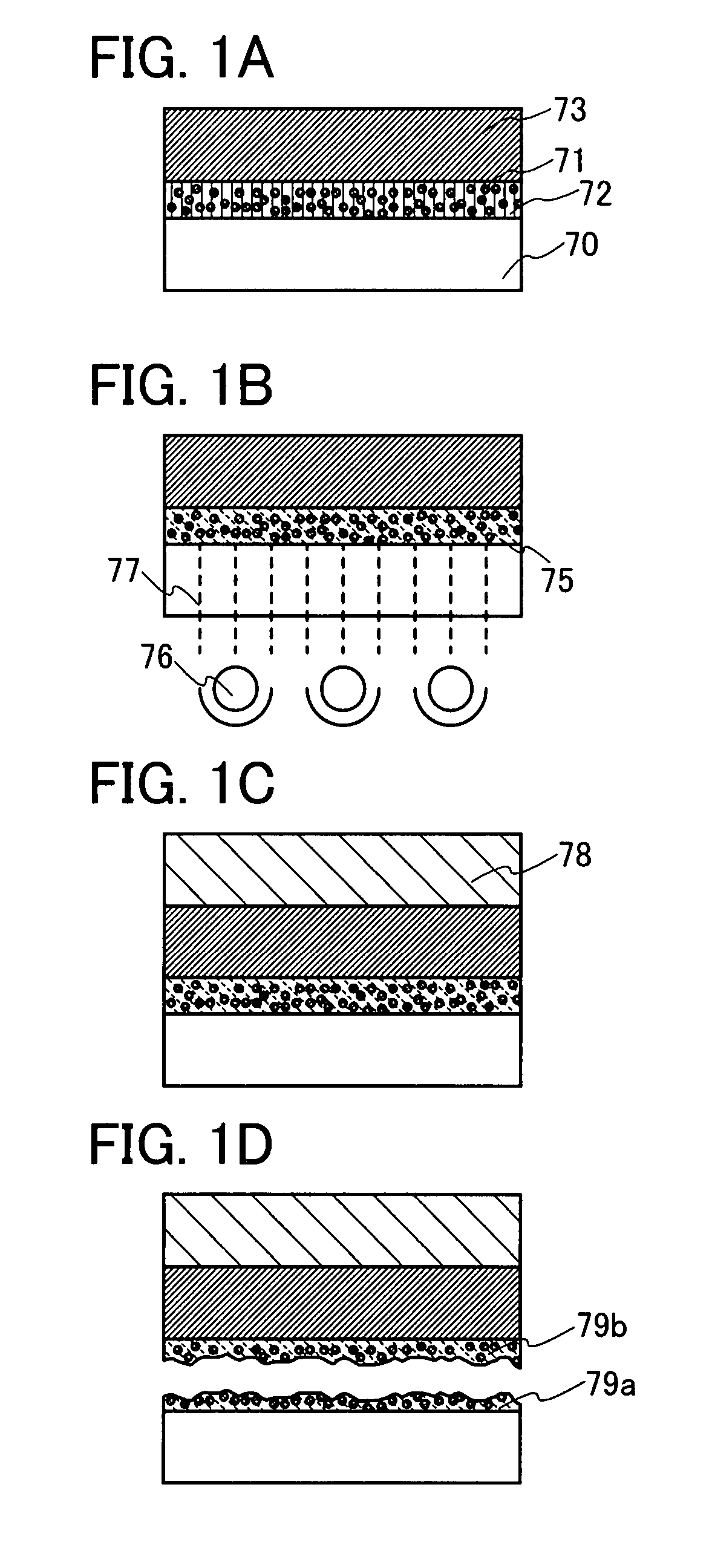
[0066]An embodiment mode of the present invention is described with reference to FIGS. 1A to 1D.

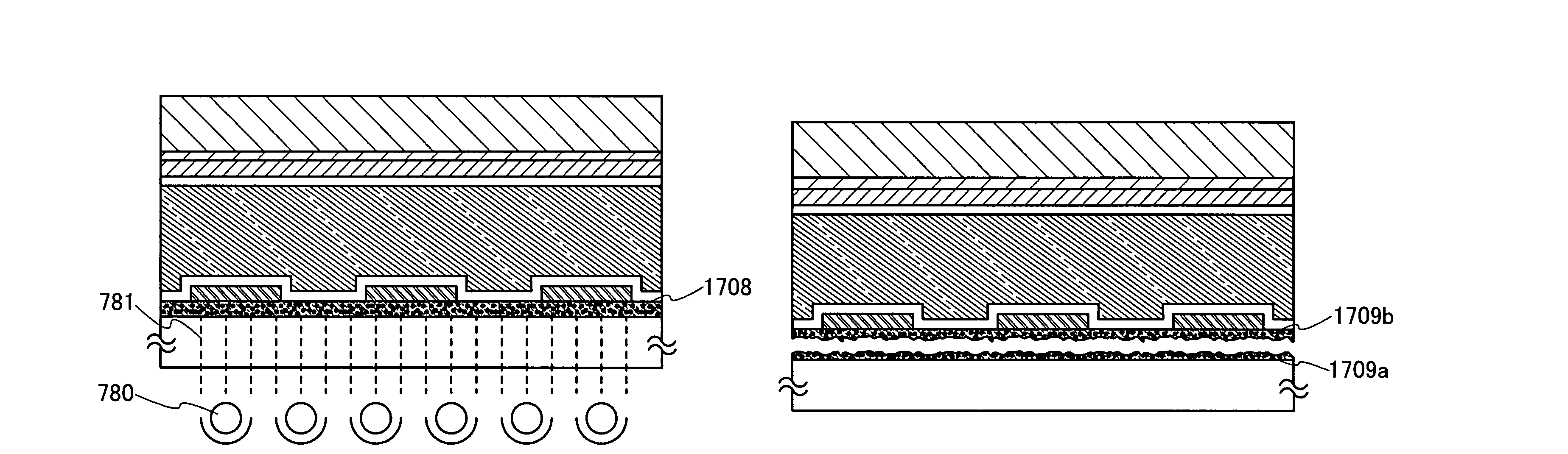
[0067]According to the present invention, when an element layer is formed over a substrate, an organic compound layer including a substance having a photocatalyst function (hereinafter, also a photocatalyst substance) is provided between the substrate and the element layer. The photocatalyst substance absorbs light, and thus, the photocatalyst substance is activated by the light. The activation energy acts on peripheral organic compound, and as a result, changes and modifies properties of the organic compound. In other words, by the energy of the activated photocatalyst substance (oxidizability), a carbon-hydrogen bond and a carbon-carbon bond of such organic compound are separated, and a part of the organic compound becomes carbon dioxide and water, and is degassed. Consequently, the organic compound layer including a photocatalyst substance becomes rough and is separated (sectioned) to ...

embodiment mode 2

[0101]Embodiment Mode 2 will explain one structural example of a display device to which a transfer process of the present invention is applied, with reference to drawings. More specifically, a case where a structure of a display device is a passive matrix type will be shown.

[0102]The display device includes first electrode layers 751a, 751b, and 751c extending in a first direction; an electroluminescent layer 752 provided to cover the first electrode layers 751a, 751b, and 751c; and second electrode layers 753a, 753b, and 753c extending in a second direction perpendicular to the first direction (FIG. 5A). The electroluminescent layer 752 is provided between the first electrode layers 751a, 751b, and 751c and the second electrode layers 753a, 753b, and 753c. In addition, an insulating layer 754 functioning as a protection film is provided so as to cover the second electrode layers 753a, 753b, and 753c. The element layer including the first electrode layers 751a, 751b and 751c, the s...


PUM


Abstract

The present invention provides a manufacturing technique of a semiconductor device and a display device using a peeling process, in which a transfer process can be conducted with a good state in which a shape and property of an element before peeling are kept. Further, the present invention provides a manufacturing technique of more highly reliable semiconductor devices and display devices with high yield without complicating the apparatus and the process for manufacturing. According to the present invention, an organic compound layer including a photocatalyst substance is formed over a first substrate having a light-transmitting property, an element layer is formed over the organic compound layer including a photocatalyst substance, the organic compound layer including a photocatalyst substance is irradiated with light which has passed through the first substrate, and the element layer is peeled from the first substrate.

Description

BACKGROUND OF THE INVENTION[0001]1. Field of the Invention[0002]The present invention relates to a method for manufacturing a semiconductor device.[0003]2. Description of the Related Art[0004]In recent years, individual recognition technology has attracted attention. For example, there is a technology which is used for production and management, in which an ID (an individual recognition code) is given to an individual object to clarify information such as a history of the object. Above all, the development of semiconductor devices that can send and receive data without contact has been advanced. As such semiconductor devices, in particular, an RFID (Radio Frequency Identification) tag (also referred to as an ID tag, an IC tag, IC chip, an RF (Radio Frequency) tag, a wireless tag, an electronic tag, or a wireless chip) has begun to be used in companies, markets, and the like.[0005]Many of such semiconductor devices each have a circuit using a semiconductor substrate such as a Si subs...

Claims


Application Information

Patent Timeline
Patent Type & Authority Patents(United States)
IPC IPC(8): H01L21/30H01L21/46
CPCH01L27/1214H01L33/62H01L27/153H01L27/1266Y02E10/549Y02P70/50H10K77/10H10K77/111H10K50/828H01L33/0093H10K71/80G02F1/133305G02F1/133603H01L21/6835H01L2221/68318H01L2221/68386
Inventor JINBO, YASUHIROMORISUE, MASAFUMIKIMURA, HAJIMEYAMAZAKI, SHUNPEI
Owner SEMICON ENERGY LAB CO LTD
Why Eureka
Try Eureka