
Dielectric sensing method and system

a sensing method and dielectric technology, applied in the field of dielectric sensing methods and systems, can solve the problems of large and relatively expensive optical measurement apparatuses, inability to utilize optical methods, and high detection sensitivities, so as to improve the signal-to-noise ratio in capacitance measurement, ensure rigidity and mechanical stability, and small changes in

Inactive Publication Date: 2012-08-21
LINAK AS +1
View PDF22 Cites 21 Cited by
  • Summary
  • Abstract
  • Description
  • Claims
  • Application Information

AI Technical Summary

Benefits of technology

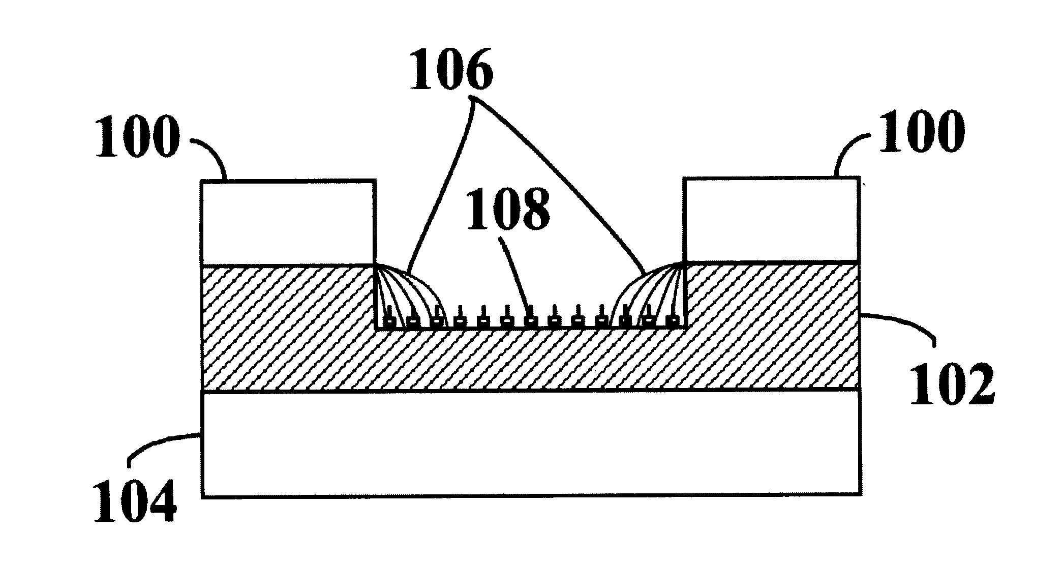
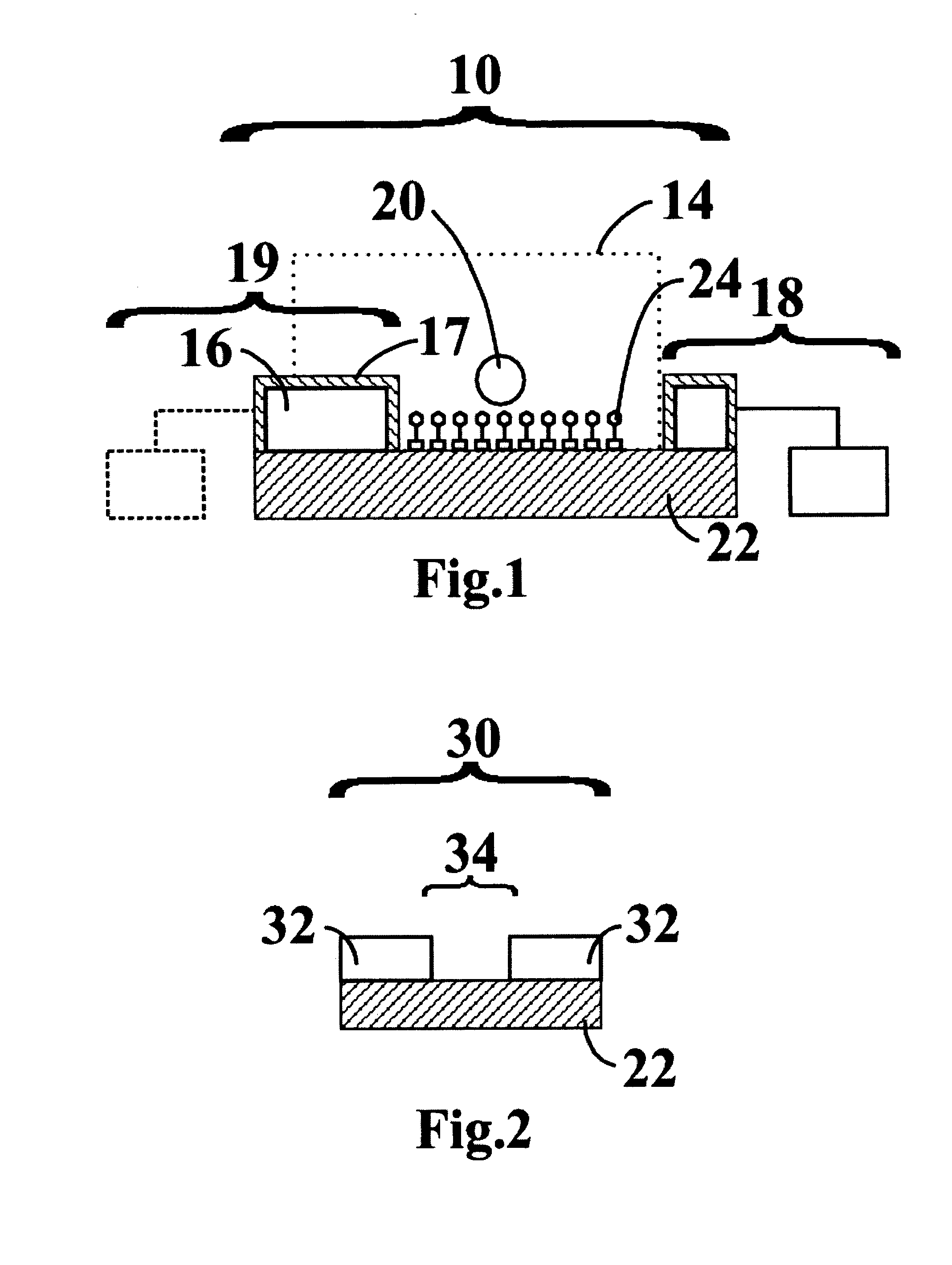
The present invention provides a dielectric sensing device and method for detecting target analytes of interest. The device includes a rigid architecture with electrodes integrated on it, which ensures mechanical stability. The electrodes are designed with sizes and separations that optimize signal-to-noise ratio. The device can also include chemical and biological discrimination elements to enhance detection of target analytes. The method involves applying a time-dependent electric field and detecting changes in the effective dielectric constant sensed by the electrodes, caused by the target analyte. The device can be used in separation apparatuses to detect target analytes of interest. The invention provides a separation apparatus with a material through which the target analyte and other species travel at different rates, and a sensing system for sensing the target analyte with high sensitivity and low fabrication cost.

Problems solved by technology

Apparatus for optical measurements can include UV lamps, lasers, lenses, detectors, and other optical elements and tend to be large and relatively expensive.
Also, often target analytes of interest and other species do not have UV or visible absorption features that are suitable and optical methods cannot be utilized.
Further, many biological target analytes of interest, for example proteins, are frequently obtained only in small quantities so that very high detection sensitivities and high-signal-to-noise ratio are required.
However, this requires modifying the target analyte of interest, which is usually undesirable, and requires significant labour, time and, as a result, expense.
Since the index of refraction of the solvent varies significantly as the fractions of components vary, it is difficult to detect small changes in index of refraction induced by small amounts of target analytes of interest.
Resistance-based methods and devices are limited by a competition between influences of target analytes of interest vs. those of media such as water, and the like which are conducting.
As a result, sensitivity can be limited in devices and methods that require operation in such media and that attempt to detect target analytes of interest directly.
To overcome such difficulties, devices and methods may employ amplification of sensitivity (e.g. through use of enzymes to generate significant product to signal detection) or removal of devices from such media; however, these approaches require additional steps and, therefore, resources such as time, expense, etc.
As the cells attach and flatten out on the electrode surface, they cause large changes in electrical impedance of the system.
Increasing ω also results in larger changes in measured voltage.
If the volume sensed by the electric fields is too small, then only a small portion of space occupied by target analytes of interest will be sensed, which is undesirable.
If the volume is too large, then the change in ∈ induced by the target analytes of interest will be small, which, too, is undesirable.
As solvent composition changes during gradient elution, there arises a large change in bulk properties, making detection of small changes generated by target analytes of interest difficult.
Determination of capacitative impedance, and therefore, small changes in ∈ become difficult.

Method used


Image

  • Dielectric sensing method and system
  • Dielectric sensing method and system
  • Dielectric sensing method and system

Examples


example

[0093]Referring to FIG. 7, in an application of the present invention to column liquid chromatography, the dielectric sensing system comprises a housing 142, a dielectric sensor 140 and an electric circuit 144.

[0094]The housing 142 may be made of Teflon or polyetheretherketones, because of their chemical stability against many chemical substances and because they are easily machined. The housing 142 may comprise a hollow block of Teflon or polyetheretherketones, one end of which fits into the bottom of a separation column. Target analytes of interest and other species may flow in solution through the housing 142, where the dielectric sensor 140 is placed.

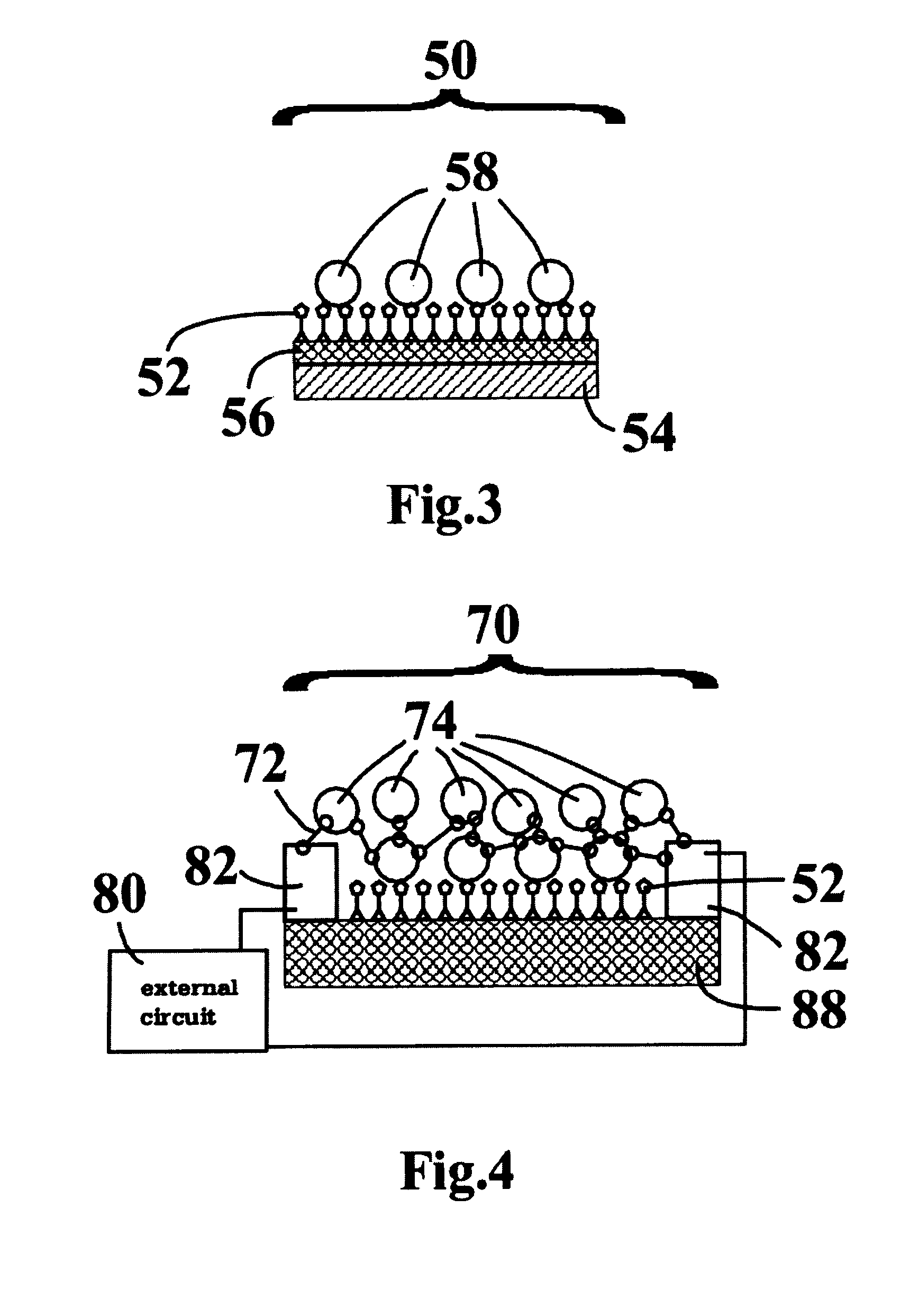
[0095]In one embodiment of the invention, the dielectric sensor 140 for sensing nano-scale target analytes of interest may be prepared by referring to publications by, for example, Musick et al. (1997) and Brust et al. (1998) which are listed among cited references and describe self-assembly of molecularly-linked nanoparticle films ...


PUM

PropertyMeasurementUnit
sizeaaaaaaaaaa
sizeaaaaaaaaaa
electric fieldaaaaaaaaaa

Abstract

Sensing device and method for detecting presence and concentration of generic target analytes of interest. The device and method are based on detecting changes in effective dielectric induced by the target analytes of interest. Applications of the invention include, but are not restricted to, detecting and characterizing the presence of chemical and / or biological target analytes of interest as well as detecting and characterizing target analytes of interest from a separation apparatus. In one embodiment of the invention, the device comprises at least two electrodes in a rigid architecture such as a solid surface, where the electrodes have sizes and inter-electrode spacings that are on the order of sizes of target analytes of interest to improve sensitivity of the device. Changes in effective dielectric and, therefore, capacitance induced by a presence of the target analytes of interest are measured electronically. The changes are used to detect the presence of the target analytes of interest and to characterize their presence.

Description

CROSS REFERENCE TO RELATED U.S. APPLICATIONS[0001]This patent application is a National Phase application claiming the benefit of PCT / CA2007 / 000429 filed on Mar. 16, 2007; which further and claims the priority benefit from, United States Provisional Patent Application Ser. No. 60 / 782,542 filed on Mar. 16, 2006, in English, entitled DIELECTRIC SENSING METHOD AND SYSTEM, and which is incorporated herein by reference in its entirety.FIELD OF THE INVENTION[0002]The present invention relates to a method and device for detecting the presence of chemical and / or biological target analytes of interest using dielectric sensing.BACKGROUND OF THE INVENTION[0003]A huge amount of chemical substances are processed in many fields, including those related to chemicals, pharmaceuticals, biology and medicine. In such fields, there is frequently a requirement that a target analyte of interest has to be separated from a mixture. For example, in fields such as chemical and pharmaceutical industries, chem...

Claims


Application Information

Patent Timeline
Patent Type & Authority Patents(United States)
IPC IPC(8): G01N27/00
CPCG01N30/64G01N27/3278G01N2030/645G01N27/22G01N27/447
Inventor DHIRANI, AL-AMINSUGANUMA, YOSHINORI
Owner LINAK AS
Learn More