Planar connector

a technology of connectors and connectors, applied in the direction of inorganic insulators, coupling device connections, plastic/resin/waxes insulators, etc., can solve the problems of above jp and inability to meet the requirements in some cases, and achieve the effect of good moldability, small resin portion width, and excellent flatness of thus produced connectors

Inactive Publication Date: 2012-09-25
POLYPLASTICS CO LTD
View PDF21 Cites 26 Cited by
  • Summary
  • Abstract
  • Description
  • Claims
  • Application Information

AI Technical Summary

Benefits of technology

[0009]In consideration of the above problems, the inventors of the present invention have conducted a detailed study to provide a planar connector made of a liquid crystalline polymer, having good performance balance and applicable to the changes in shape of the recent planar connectors, and found that there can be obtained a planar connector having excellent performances such as good moldability, flatness, warp-deformation resistance, heat resistance, and the like through the use of a composite resin composition prepared by blending (A) a liquid crystalline polymer with (B) a plate-like inorganic filler and (C) a specified fibrous filler, at a specified ratio, thus having perfected the present invention.
[0017]If the content of p-hydroxy benzoic acid residue exceeds 55% by mole, the flowability deteriorates because of the solidification rate or the like during cooling, caused by the difference in the state of crystallization of polymer, which fails to form a planar connector having good properties. In addition, the melting point of the liquid crystalline polymer is required to be 330° C. or higher. To mount the planar connector on a circuit board and to form an electronic circuit, there is applied soldering which has functions of fixation and circuit-formation. The soldering is executed by letting the circuit board with the planar connector pass through an infrared reflow furnace. To prevent changes such as deformation on the connector in the infrared reflow furnace, the melting point of the liquid crystalline polymer is required to be 330° C. or more.
[0027]In particular, the content of structural unit of (IV) within the range of 3 to 6% by mole is preferred because a connector having a high-strength lattice area and having good flatness (low warpage deformation) can be obtained.
[0035]The polymer produced by the above polymerization method can further increase the molecular weight thereof through the use of the solid-phase polymerization which heats the polymer under atmospheric pressure or reduced pressure, or in an inert gas atmosphere. A preferred condition of the solid-phase polymerization includes the reaction temperature within the range of 230° C. to 350° C., preferably 260° C. to 330° C., and the ultimate pressure within the range of 10 to 760 Torr (or 1,330 to 101,080 Pa).
[0044]As shown in FIG. 1, the use of the composite resin composition according to the present invention makes it possible to mold the very thin planar connector with good moldability, having a difference in thickness between the outer frame and the lattice area, and having very small width of the resin portion of the lattice area in that the lattice part pitch interval is 1.5 mm or less (1.2 mm), the thickness ratio of the lattice area to the outer frame area is 0.8 or less (0.5), and the width of resin portion of the lattice area for holding the terminals is 0.5 mm or less (0.18mm). The flatness of thus produced connector is also excellent.

Problems solved by technology

However, by factors such as the shape change accompanied with the increase in the integration rate and the like, specifically increase in the number of connector pins and decrease in the width of lattice area, it was found that the above JP-A 2005-276758 cannot cope with the requirements in some cases.

Method used


Image

  • Planar connector
  • Planar connector
  • Planar connector

Examples


examples

[0052]The present invention will be described below referring to the examples. The present invention, however, is not limited to the examples. The measurement of physical properties and the test were given by the following-described methods.

[0053](1) Apparent Melt Viscosity

[0054]The apparent melt viscosity was measured in accordance with ISO 11443 by using Capillary Rheometer (L=20 mm, d=1 mm, Capillograph 1B, manufactured by Toyo Seiki Seisakusho, Ltd.) at a temperature of 360° C. and at a shear rate of 1000 / s. The measurement temperature was 380° C. for the liquid crystalline polymer 1 and the liquid crystalline polymer 2, 350° C. for the liquid crystalline polymer 3, and 360° C. for the liquid crystalline polymer 4.

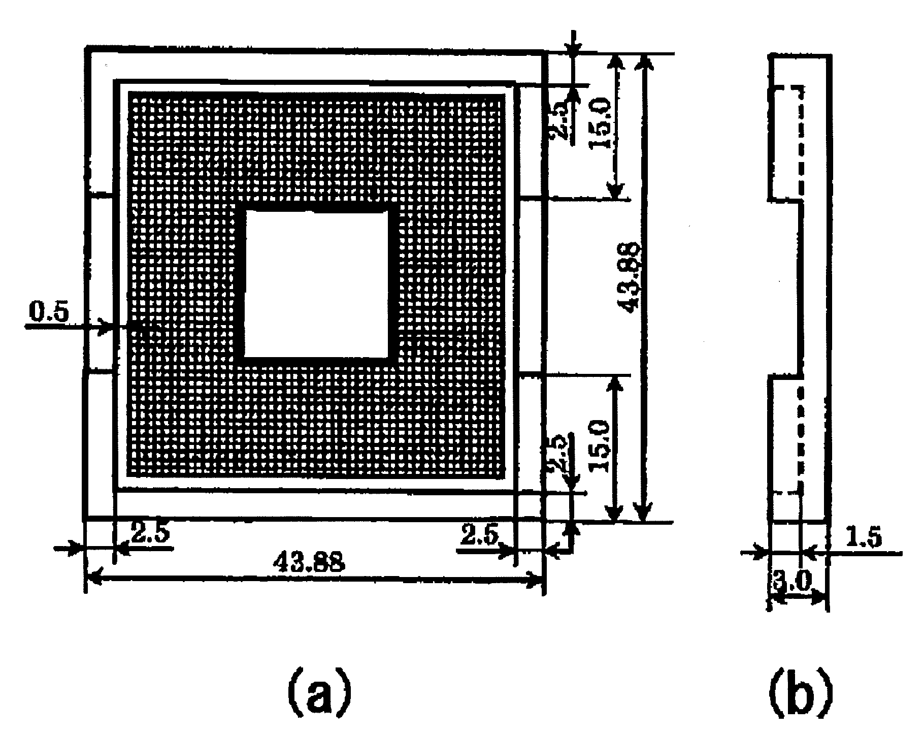
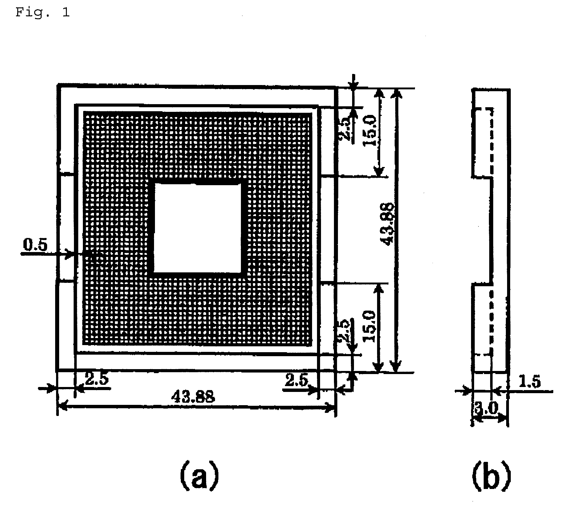
[0055](2) Measurement of Flatness of Connector

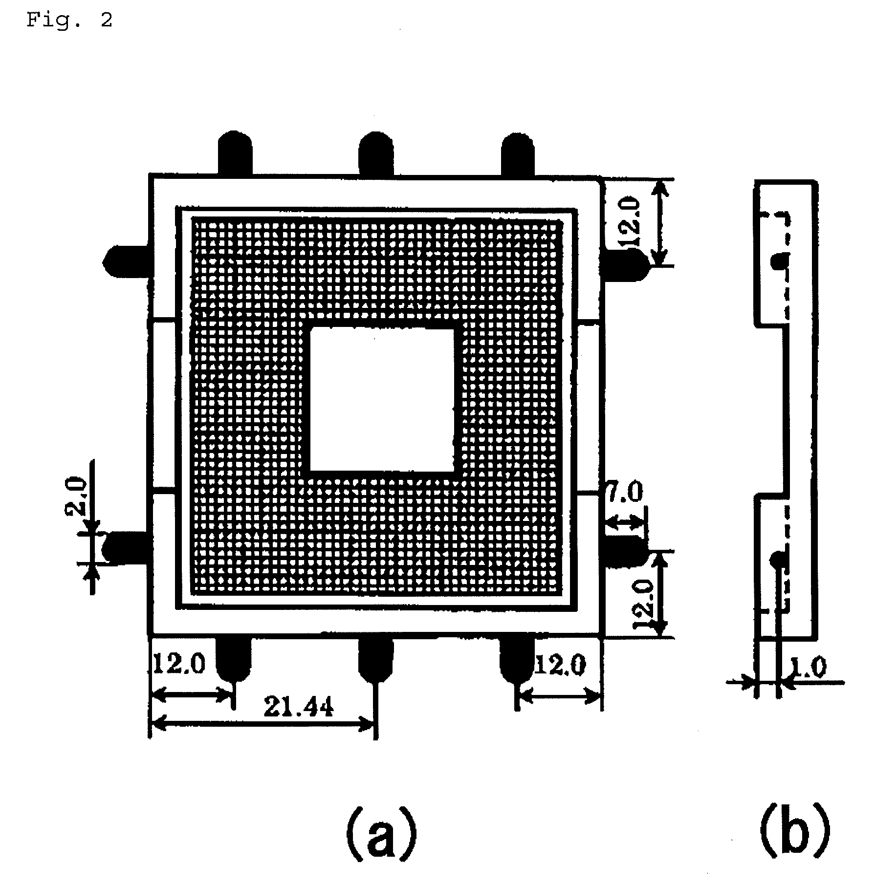
[0056]The planar connector (1248 pin holes) illustrated in FIG. 1 was molded by injection molding from the resin composition pellets under the condition given below. The planar connector had the entire size of 43.88 mm×43.8...

examples 1 to 7

, Comparative Examples 1 to 8

[0112]Evaluation was carried out on specimens of liquid crystalline polymer compositions containing a plate-like filler and a fibrous filler, under the condition given below. The results are shown in Table 1. In Comparative Example 8, no good specimen was obtained by injection molding.

[0113][Manufacturing Condition]

[0114](Applied Components)

[0115](A) Liquid Crystalline Polymer

[0116]Liquid crystalline polymer 1

[0117]The following raw material monomers, metal catalyst, and acylation agent were supplied to a polymerization vessel equipped with an agitator, a reflux column, a monomer-supply opening, a nitrogen inlet, and an evacuation / discharge line.[0118](I) 6-Hydroxy-2-naphthoic acid 1218 g (48% by mole) (HNA)[0119](II) Terephthalic acid 560 g (25% by mole) (TA)[0120](III) 4,4′-Dihydroxy biphenyl 628 g (25% bymole) (BP)[0121](IV) 4-Hydroxy benzoic acid 37 g (2% by mole) (HBA)[0122]Potassium acetate catalyst (catalyst amount)[0123]Acetic anhydride (1.04 tim...


PUM

PropertyMeasurementUnit
thicknessaaaaaaaaaa
lengthaaaaaaaaaa
melting pointaaaaaaaaaa

Abstract

The present invention provides a planar connector having excellent performances including flatness, warp-deformation resistance, and heat resistance, being capable of responding to shape changes in recent planar connectors. Specifically, the planar connector is composed of a composite resin composition comprises (A) a liquid crystalline polymer containing 55% by mole or less of p-hydroxy benzoic acid residue and having a melting point of 330° C. or higher, (B) a plate-like inorganic filler, and (C) a fibrous filler having a weight average fiber length within a range of 250 to 600 μm, the amount of (B) component being 25 to 35% by weight to the total composition, the amount of (C) component being 10 to 25% by weight to the total composition, the sum in total of (B) component and (C) component being 40 to 50% by weight to the total composition, wherein the connector has a lattice structure inside an outer frame, and has an opening inside the lattice area, and wherein the pitch interval of the lattice area is 1.5 mm or less, and the ratio of the thickness of the thickness of the lattice area to the outer frame area is 0.8 or less.

Description

TECHNICAL FIELD[0001]The present invention relates to a planar connector having a lattice structure within the outer frame, being used for CPU socket, and the like.BACKGROUND ART[0002]Among thermoplastic resins, liquid crystalline polymers are known as the materials having excellent dimensional accuracy, damping function, and flowability, and generating very few flash during molding thereof. Due to these advantageous features, the liquid crystalline polymers have been widely adopted as the materials of various kinds of electronic parts.[0003]In particular, connectors in recent years are requested to have increased performance of higher heat resistance (aiming at the increase in productivity by the advanced mounting technology), higher density (multi-pin), and smaller size than ever, accompanied with the increase in performance of electronics devices. By taking advantage of features of the above-mentioned liquid crystalline polymers, liquid crystalline polymer compositions reinforced...

Claims


Application Information

Patent Timeline
Patent Type & Authority Patents(United States)
IPC IPC(8): H01R24/00C08K3/34C08K7/02C09K19/38C08L67/02
CPCC08K7/28C08K3/34
Inventor FUKATSU, HIROKINISHIKAWA, RAITAOHSHIBA, HIROKAZUKAYUKAWA, SEIJIWATANABE, KAZUFUMI
Owner POLYPLASTICS CO LTD
Why Eureka
Try Eureka