Balloon catheter for delivering therapeutic agents

a balloon catheter and therapeutic agent technology, applied in the direction of catheters, packaged goods, packaged foodstuffs, etc., can solve the problems of excessive production of extra cellular matrices (ecm), recurring obstructions, and reoccurring restrictions or blockages, so as to achieve convenient, efficient and cost-effective

Inactive Publication Date: 2012-10-02
ABBOTT CARDIOVASCULAR
View PDF36 Cites 6 Cited by
  • Summary
  • Abstract
  • Description
  • Claims
  • Application Information

AI Technical Summary

Benefits of technology

[0010]In view of the above, it is apparent that there is a need to provide a drug delivery device that delivers drugs, therapeutic agents, diagnostic fluids and the like deep within the tissue without causing damage to the tissue and significant systemic loss of delivered materials. It is also desirable that the drug delivery device allows one or more drugs to be released at adequate rates. There is also a need to provide a method of manufacturing such an improved drug delivery device that is convenient, efficient, and cost effective.
[0011]In one embodiment of the present invention, the drug delivery device includes an elongated shaft, having a distal end and a proximal end, and an inflation assembly coupled to the distal end of the elongated shaft. The inflation assembly includes an inflatable balloon having a plurality of holes formed in the wall of the balloon. Further, a microporous coating covers a portion of the outer surface of the wall of the balloon. The thickness of the coating and the size of the micropores permit controlled delivery of a substance from the elongated shaft to the holes in the balloon and through the micropores of the coating covering the balloon.
[0015]In general, drug(s) flow through the elongated shaft and into the inflatable member causing the inflatable member to inflate. Upon reaching a predetermined pressure, the drug(s) stream out of the holes of the inflatable member and disseminate from the pores of the microporous coating at a controlled release rate. Generally, the flow rate of fluid from the coated inflatable member is a function of the thickness and pore size of the microporous coating. As such, the microporous coating disperses the jet-like streams of liquid ejected from the holes of the inflatable member so that the fluid oozes or controllably exudes from the microporous coating to prevent the jetting effect from damaging tissue.

Problems solved by technology

Although PTCA and related procedures aid in alleviating intraluminal constrictions, such constrictions or blockages reoccur in many cases.
The cause of these recurring obstructions, termed restenosis, is due to the body responding to the surgical procedure.
Proliferation and migration of smooth muscle cells (SMC) from the media layer of the lumen to the intima cause an excessive production of extra cellular matrices (ECM).
As such, one drawback associated with the systemic application of drugs is that areas of the body not needing treatment are also affected.
However, such devices may be deficient in their drug delivery characteristics.
Since the rate at which the drug is released or delivered to the target site is a function of the structural properties of the apertures, drug release rates are inadequately controlled.
As such, the balloon configuration greatly limits the usefulness of the catheter.
The detriment in using a polymeric coating on the balloon, on the other hand, is that the polymer may prevent an adequate release of the drug at the target site during and subsequent to the inflation of the balloon.
The window of opportunity for application of a drug by a balloon is very short.
A polymeric coating may not allow for the drug to elute or be release from the coating quickly enough.

Method used


Image

  • Balloon catheter for delivering therapeutic agents
  • Balloon catheter for delivering therapeutic agents
  • Balloon catheter for delivering therapeutic agents

Examples


example 1

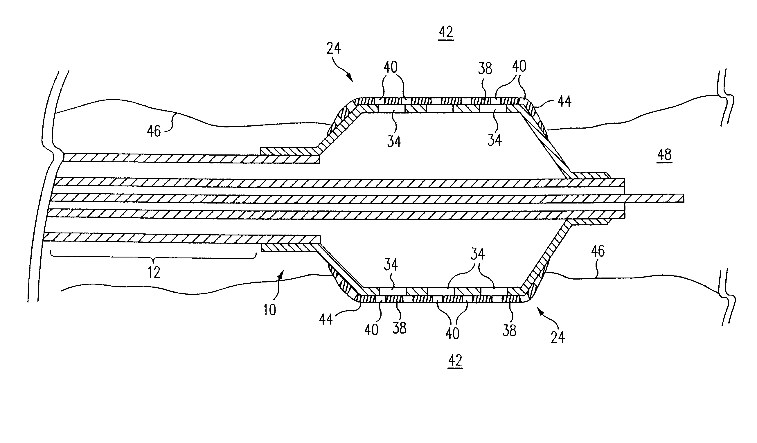
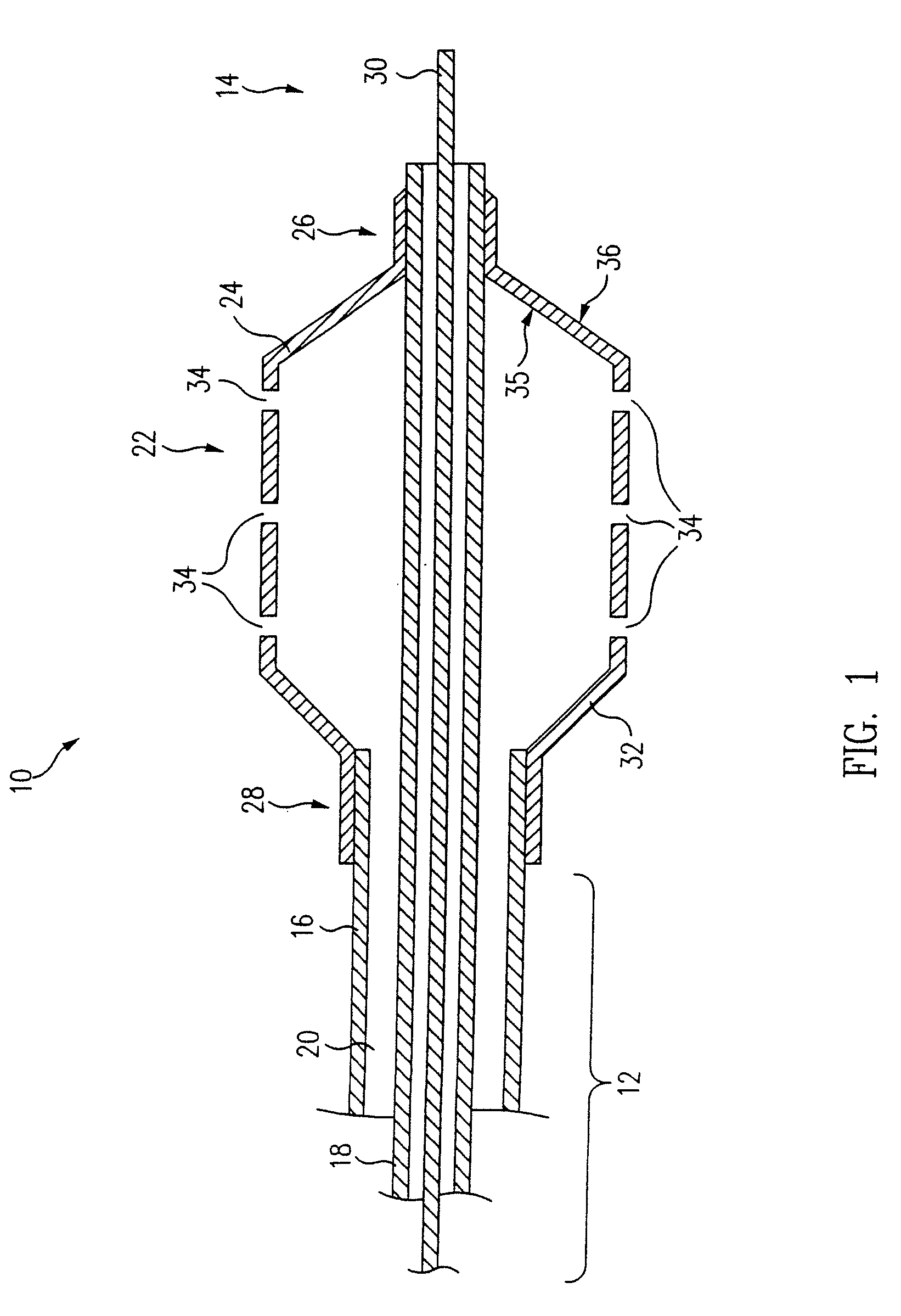
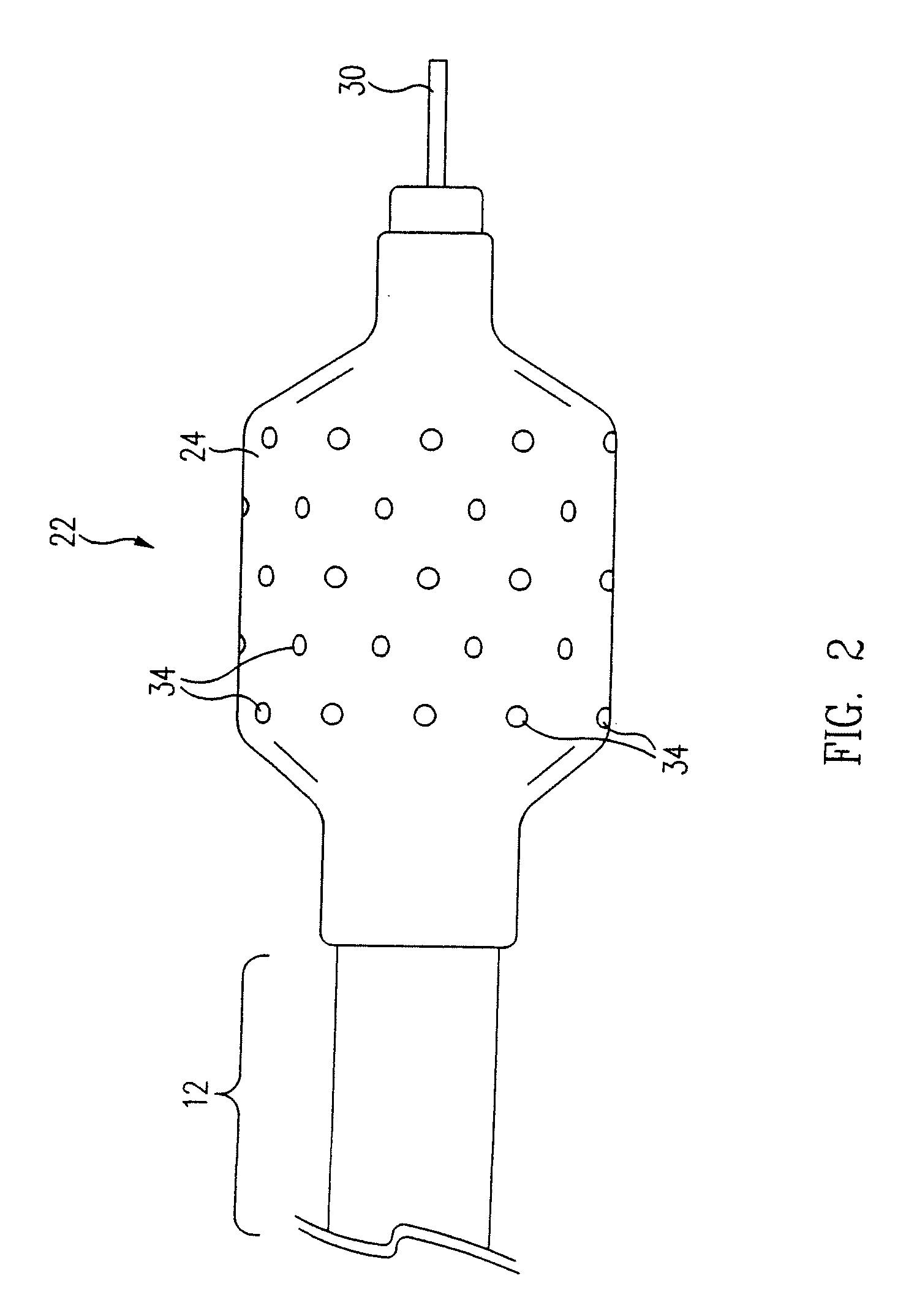
[0046]The inflatable member 24 of a balloon catheter 10 having a plurality of holes 34 formed in the wall 32 of the 30 mm by 20 mm (1.18 inch by 0.79 inch) balloon 24 is suspended from a fixture (not shown) and partially inflated. In one embodiment, approximately 6.9 kPa-13.8 kPa (approximately 1-2 psi) of air flows from the inflation port (not shown), through the annular lumen 20, and into the inflatable balloon 24 causing the balloon 24 to partially inflate. Other fluids, such as nitrogen, at variable pressures, ranging from about 6.9 kPa-13.8 kPa (about 1 psi to 2 psi), can also be used to inflate the balloon 24. In general, the desired fluid pressure flowing through the balloon should be an amount that allows partial inflation of the balloon 24 while maintaining the structural integrity of the microporous coating 38.

[0047]A first solution, i.e. polymer solution, is formulated using 1% w / w Tecoflex® EF-600 (Termedica, Inc.) dissolved in THF / 1.4 Dioxane mixture (2:1). Note that “w...

example 2

[0049]The inflatable member 24 of a balloon catheter 10 having a plurality of holes 34 formed in the wall 32 of a 30 mm by 20 mm (1.18 inch by 0.79 inch) balloon 24 is completely deflated to a flattened configuration, as shown in FIG. 5. A first solution, i.e. polymer solution, is formulated using 1% w / w Tecoflex® EF-600 (Termedica, Inc.) dissolved in THF / 1.4 Dioxane mixture (2:1). The polymer solution and a second solution, or non-solvent such as water, are carefully mixed to avoid precipitation during the mixing process. In one embodiment, the concentration / ratio of polymer solution to non-solvent is approximately 90:10. A coating or layer of the mixture is then applied to the balloon 24 via dipping, spraying or other appropriate application techniques. The total volume of the mixture contained in each layer depends on the desired balloon configuration. In one embodiment, a coating thickness of 0.01 mm (3.94×10⁻⁴ inch) is applied to the 30 mm by 20 mm (1.18 inch by 0.79 inch) ball...


PUM

PropertyMeasurementUnit
sizeaaaaaaaaaa
thicknessaaaaaaaaaa
pressureaaaaaaaaaa

Abstract

A drug delivery device for delivering therapeutic agents and a method of making such a device is disclosed. The device includes an inflatable balloon. A microporous coating covers a portion of the outer surface of the wall of the balloon. The thickness of the coating and the size of the micropores can permit desirable delivery of a substance from the micropores of the coating and into the tissue of a patient's lumen.

Description

CROSS REFERENCE TO RELATED APPLICATIONS[0001]This is a continuation-in-part application of U.S. patent application Ser. No. 11 / 508,609, filed Aug. 22, 2006 and issued as U.S. Pat. No. 7,658,966 on Feb. 9, 2010, which is a divisional of U.S. patent application Ser. No. 10 / 365,255, filed Feb. 11, 2003 and issued as U.S. Pat. No. 7,115,299 on Oct. 3, 2006, which is a divisional of U.S. patent application Ser. No. 09 / 755,386, filed on Jan. 5, 2001 and issued as U.S. Pat. No. 6,544,223 on Apr., 8, 2003.FIELD OF THE INVENTION[0002]The present invention relates to a device and method of making a porous membrane. More specifically, this invention relates to a microporous membrane that can be formed on the outer surface of the inflatable member of a balloon catheter.BACKGROUND OF THE INVENTION[0003]A variety of surgical procedures and medical devices are currently used to relieve intraluminal constrictions caused by disease or tissue trauma. An example of one such procedure is percutaneous t...

Claims


Application Information

Patent Timeline
Patent Type & Authority Patents(United States)
IPC IPC(8): B05D3/10A61M25/10A61F2/958
CPCA61L29/085A61L29/146A61L29/16A61M25/10A61M25/1027A61L2300/606A61M2025/105A61M2025/1075A61L2420/02
Inventor KOKISH, LYUDMILAPACETTI, STEPHEN D.STANKUS, JOHN
Owner ABBOTT CARDIOVASCULAR
Why Eureka
Try Eureka