
Portable combustion device utilizing thermoelectrical generation

a technology of thermoelectric generation and combustion device, which is applied in the direction of domestic stoves or ranges, ways, heating types, etc., can solve the problems of inability to obtain a new canister of gas or liquid fuel, difficulty in ensuring the safety of users, so as to achieve efficient overall combustion and reduce the kindling period

Active Publication Date: 2012-10-30
BIOLITE INC
View PDF18 Cites 55 Cited by
  • Summary
  • Abstract
  • Description
  • Claims
  • Application Information

AI Technical Summary

Benefits of technology

"The invention is a portable combustion device that uses a fan to direct airflow over the fuel, reducing smoke and improving combustion efficiency. The device has a housing that encloses a thermoelectric generator (TEG) and a heat-conducting probe to transfer heat from the flame to the TEG. The TEG generates electrical current based on the difference in temperature between the sides of the TEG. The device also has a heat-sink with a plurality of vanes that cool the TEG and promote more efficient combustion. The fan-driven airflow helps to cool the hot inner walls of the combustion chamber, insulating the TEG from the hot inner walls and promoting quicker kindling and more efficient combustion. The device can be used with a variety of biomass fuels and does not require an external power supply. The invention provides a cleaner burning of biomass fuels and a more efficient use of the TEG."

Problems solved by technology

While previous devices did provide a combustion device, they all had the similar drawback that they all required a special fuel source.
The availability of fuel poses a serious drawback should the canister run out, especially if used for hiking, or emergency situations.
Likely, it is impossible to obtain a new canister of gas or liquid fuel while out camping or during an emergency, and even if it is possible, there is no guarantee that the person would be able to find replacements for their type of fuel and canister.
Moreover, should a person need to use their portable combustion device for an extended length of time, carrying a multitude of canisters for fuel becomes impractical.
Since the canisters are often under pressure and most fuels are harmful or toxic, the canisters can not be left behind at a campsite, or during an emergency scenario.
With a variety of fuels, canister types, and portable combustion devices, which are all made by different companies a person would limited in their options and be forced to continue to use a single fuel source.
Generally the biomass combustion is carried out in some form of simple fire-driven stove, which is used for both heating and cooking However, biomass devices typically have drawbacks that render them undesirable in many situations.
For example, biomass stoves are not “clean” burning, that is they produce soot and smoke during the combustion process, which can cover pots, pans, or even food during the combustion.
Also, the smoke generated during the combustion process can make the biomass stoves potentially dangerous for indoor use—as the smoke contains large quantities of soot and other toxic combustion products, including carbon monoxide.
Nevertheless, such stoves are often used in small indoor spaces with inadequate ventilation in developing countries.
In addition, many biomass stoves are heavy, making them less suitable for field use, as they are not easily portable.
However, batteries may have a short life in use, and / or be discharged (dead), or be in need of recharging, when needed.
In addition, batteries are expensive and often unavailable to peoples of developing countries.
In addition, batteries are environmentally unfriendly and often disposed of improperly.

Method used


Image

  • Portable combustion device utilizing thermoelectrical generation
  • Portable combustion device utilizing thermoelectrical generation
  • Portable combustion device utilizing thermoelectrical generation

Examples


Embodiment Construction

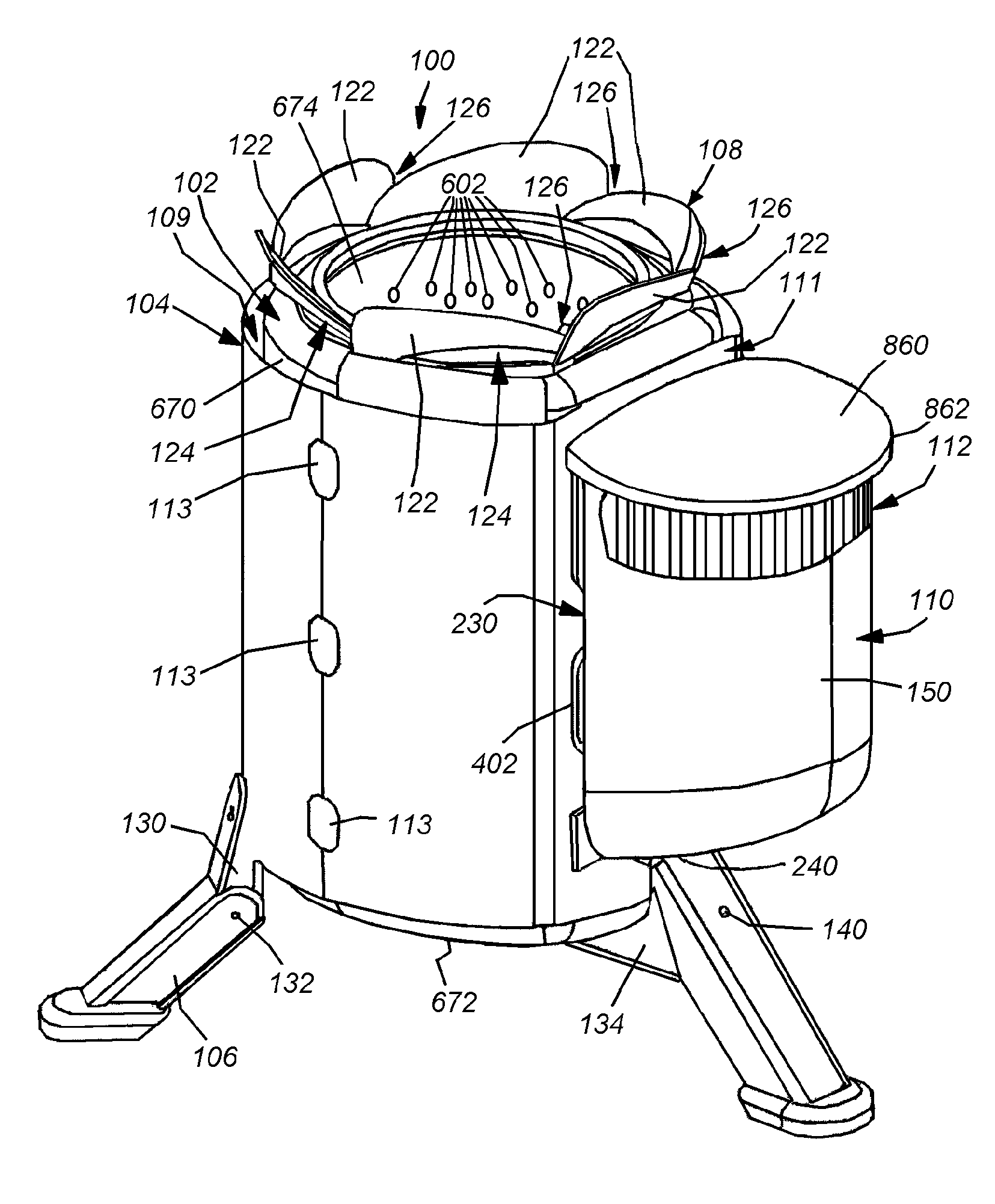
[0029]In accordance with the present invention, there is provided a portable combustion device that generates power and heat by efficiently (i.e. cleanly) burning a biomass fuel. It should be clear that, the term “biomass” can be taken broadly to include any fuel, coal, oil, waste products, etc, that will burn more cleanly and efficiently by injection of air during combustion. Likewise, a further advantage of increased efficiency in the burning of fuel is that less fuel is consumed for a given heat output.

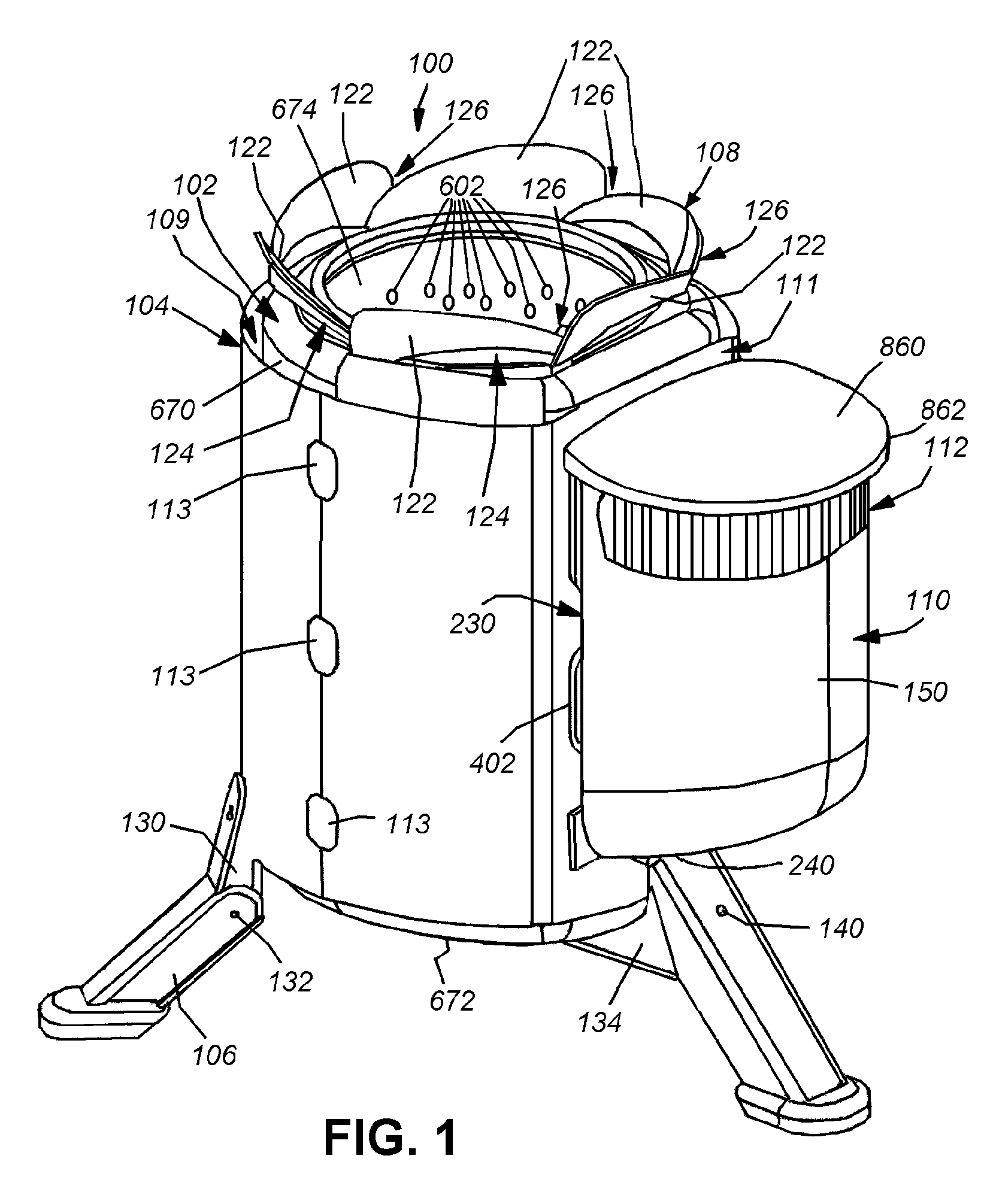
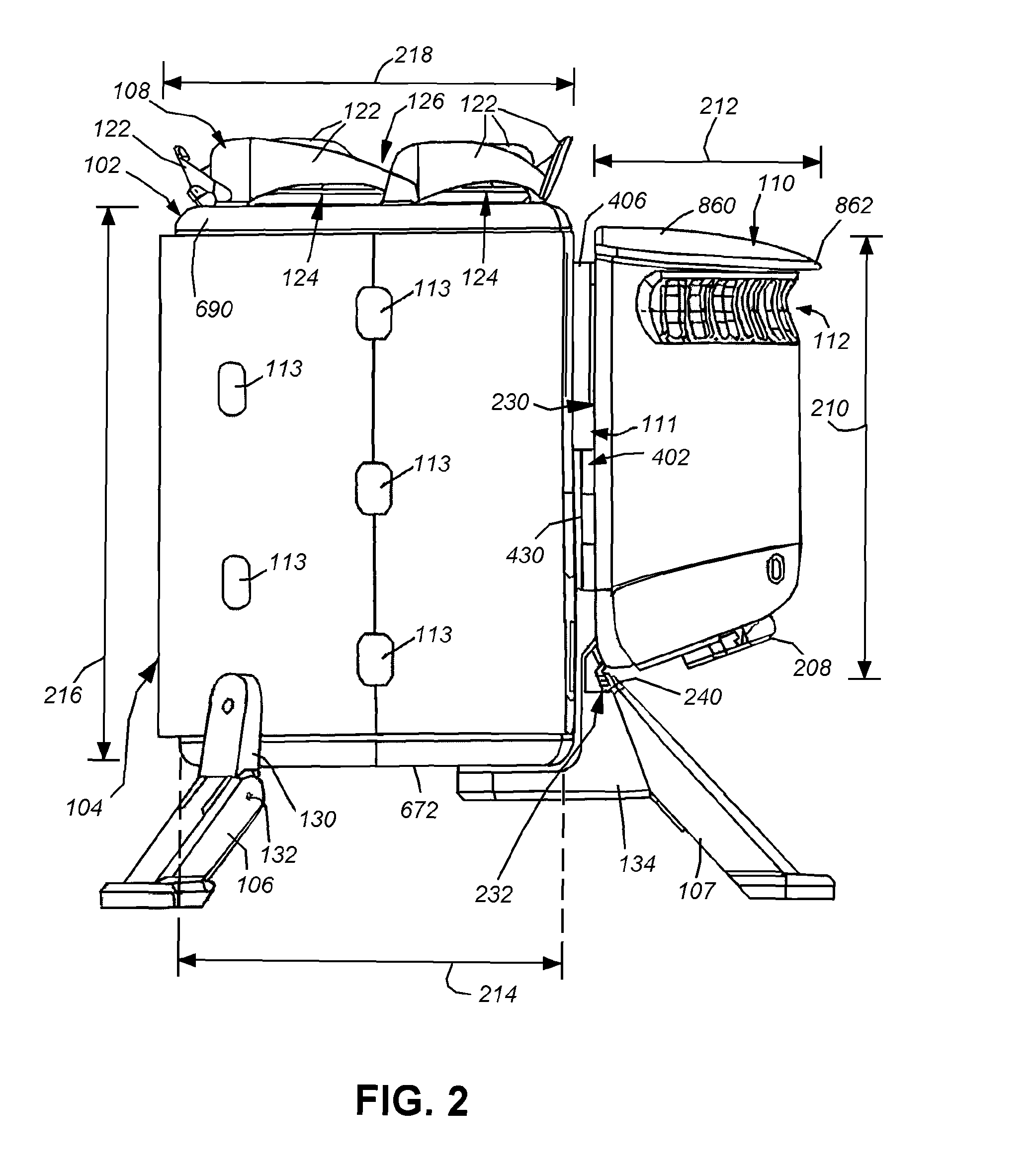
[0030]FIGS. 1-3 show various views of the portable combustion device 100 according to an illustrative embodiment of this invention. The depicted portable combustion device 100 is relatively cylindrical in shape and is comprised of an internal combustion or burn chamber 102 and a TEG (thermoelectric generator) housing 110 constructed of a durable polymer or lightweight metal, such as an aluminum casting. The combustion chamber 102 is preferably made of a lightweight, durable metal, ...


PUM


Abstract

This invention provides a portable combustion device that provides a cleaner combustion, reduces the kindling period, and provides a more efficient overall combustion through the use of a fan that directs a predetermined volume of airflow over the combustible fuel—typically wood or similar cellulose-based biological solids. The combustion device has a combustion chamber into which the fuel source is placed for combustion. Mounted to the side of the combustion chamber is a housing that encloses the TEG, which generates an electrical output based on a difference in temperature on opposing sides. Mounted onto the TEG housing and protruding into the combustion chamber through a small passageway is a heat-conducting probe and heat-conducting probe base unit. The opposing side of the TEG is also in contact with a heat sink to remove heat from the TEG device through interaction with ambient air that passes over the vanes from a port located along the side of the TEG housing. A motor and fan near the heat sink to draw air away the heat sink and aid in the cooling of the heat sink, and force air onto the combusting fuel through a plurality of peripheral ports that connect with an air space located between the inner and outer walls of the combustion chamber.

Description

RELATED APPLICATION[0001]This application claims the benefit of U.S. Provisional Application Ser. No. 61 / 103,335, entitled PORTABLE COMBUSTION DEVICE UTILIZING THERMOELECTRICAL GENERATION, by Jonathan Cedar and Alexander H. Drummond, filed Oct. 7, 2008, the teachings of which are expressly incorporated herein by reference.FIELD OF THE INVENTION[0002]The present invention relates generally to combustion devices, such as fixed and portable cooking stoves, and more particularly to combustion arrangements that provide more efficient use of combustible materials and the energy generated therefrom.BACKGROUND OF THE INVENTION[0003]There exist a variety of portable combustion devices that may be used, for example, as a stove for cooking or heating, among other uses. In the past, portable combustion devices required a variety of fuels such as those used for liquid fuel stoves, portable and fixed wood stoves and compressed gas fuel stoves. These stoves were used in a variety of different situ...

Claims


Application Information

Patent Timeline
Patent Type & Authority Patents(United States)
IPC IPC(8): F24B1/18F24B13/00
CPCF23B20/00F24B1/00F24B5/026H01L35/30F23M2900/13003Y02B40/163F23B60/00Y02B40/00H10N10/13
Inventor CEDAR, JONATHAN M.DRUMMOND, ALEXANDER H.
Owner BIOLITE INC
Learn More