Phosphorescent OLED device with mixed hosts
a phosphorescent el and host technology, applied in the direction of organic semiconductor devices, discharge tube luminescnet screens, natural mineral layered products, etc., can solve the problems of large efficiency loss, performance limitations, and many desirable applications, and achieve the effects of improving efficiency, driving voltage and operational stability, and improving luminan
- Summary
- Abstract
- Description
- Claims
- Application Information
AI Technical Summary
Benefits of technology
Problems solved by technology
Method used
Image
Examples
examples
Device Examples 1-1 through 1-6
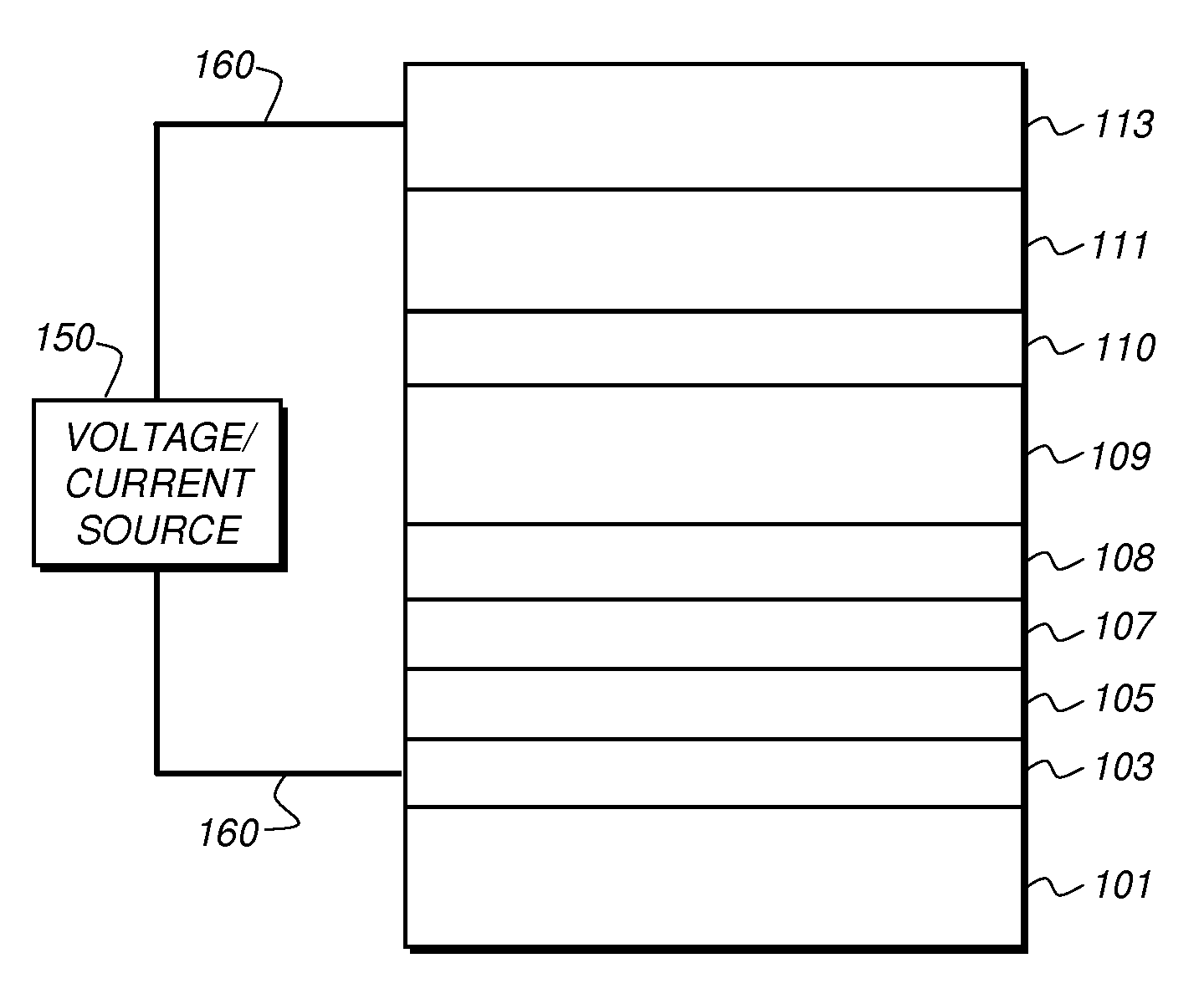
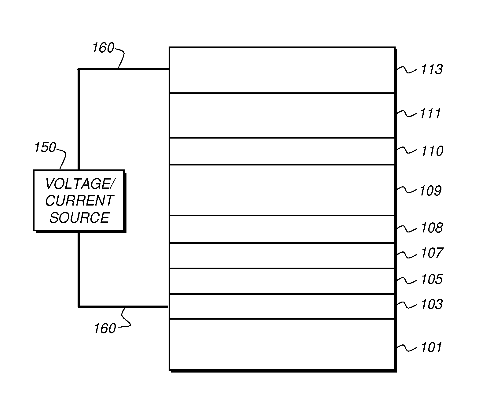
[0299]Inventive OLED devices were constructed in the following manner:[0300]1. A glass substrate, coated with an approximately 25 nm layer of indium-tin oxide (ITO) as the anode, was sequentially ultrasonicated in a commercial detergent, rinsed in deionized water, and exposed to an oxygen plasma for about 1 minute.[0301]2. Over the ITO a 1 nm fluorocarbon (CFx) hole injecting layer (HIL) was deposited by plasma-assisted deposition of CHF3 as described in U.S. Pat. No. 6,208,075.[0302]3. Next, a hole transporting layer (HTL) of NN′-di-1-naphthyl-N,N′-diphenyl-4,4′-diaminobiphenyl (NPB) was vacuum deposited to a thickness of 115 nm.[0303]4. A 35 nm light emitting layer (LEL) consisting of a mixture of GaC-1 as the electron transporting co-host, NPB as the hole transporting co-host, and fac-tris(1-phenyl-isoquinolinato-N^C)Iridium(III) [i.e., Ir(1-piq)3] as a red phosphorescent emitter was then vacuum deposited onto the HTL. Concentration of NPB was varie...
examples 5-1 through 54
Device Examples 5-1 through 54
[0374]A comparative device 5-1 not satisfying the satisfying the requirements of the invention was fabricated in the following manner:[0375]1. A glass substrate, coated with an approximately 25 nm layer of indium-tin oxide (ITO) as the anode, was sequentially ultrasonicated in a commercial detergent, rinsed in deionized water, and exposed to an oxygen plasma for about 1 minute.[0376]2. Over the ITO a 1 nm fluorocarbon (CFx) hole injecting layer (HIL) was deposited by plasma-assisted deposition of CHF3 as described in U.S. Pat. No. 6,208,075.[0377]3. Next a HTL of NPB was vacuum deposited to a thickness of 95 nm.[0378]4. An exciton / electron blocking layer (EBL) of 4,4′,4″-tris(carbazolyl)-triphenylamine (TCTA) was vacuum deposited to a thickness of 10 nm.[0379]5. A 35 nm light emitting layer (LEL) consisting of a GaC-1 as host, and tris(2-phenyl-pyridinato-N,C2′)Iridium (III) [i.e., r(ppy)3] as a green phosphorescent emitter was then vacuum deposited ont...
PUM
| Property | Measurement | Unit |
|---|---|---|
| triplet energy | aaaaa | aaaaa |
| HOMO | aaaaa | aaaaa |
| thick | aaaaa | aaaaa |
Abstract
Description
Claims
Application Information
 - R&D
- Intellectual Property
- Life Sciences
- Materials
- Tech Scout
- Unparalleled Data Quality
- Higher Quality Content
- 60% Fewer Hallucinations
Browse by: Latest US Patents, China's latest patents, Technical Efficacy Thesaurus, Application Domain, Technology Topic, Popular Technical Reports.
© 2025 PatSnap. All rights reserved.Legal|Privacy policy|Modern Slavery Act Transparency Statement|Sitemap|About US| Contact US: help@patsnap.com


