Battery internal short-circuit detection apparatus and method, and battery pack

a short-circuit detection and battery pack technology, applied in the direction of batteries, instruments, electrochemical generators, etc., can solve the problems of not recovering, unable to detect internal short-circuits, and drastic drop in cell voltag

Inactive Publication Date: 2012-12-18
GK BRIDGE 1
View PDF15 Cites 27 Cited by
  • Summary
  • Abstract
  • Description
  • Claims
  • Application Information

AI Technical Summary

Benefits of technology

[0015]An object of the present invention is to provide a battery internal short-circuit detection apparatus and method capable of securely detecting an internal short circuit in a battery in which the voltage thereof does not drop drastically even when an internal short circuit occurs, and to provide a battery pack.
[0021]As a result, an appropriate threshold current can be determined in response to the temperature of the battery, and the accuracy of detecting an internal short circuit can be improved.

Problems solved by technology

However, the problem of this structure is that if an internal short circuit occurs, the occurrence of the internal short circuit cannot be detected with a conventional method that uses a cell of a conventional structure without a porous protective film.
Specifically, in the case of the cell of a conventional structure without a porous protective film, when an internal short circuit occurs, the voltage of the cell drops drastically as shown in FIG. 3, and does not recover.
In this manner, the voltage of the cell drops drastically and the temperature of the cell increases drastically due to thermal runaway.
The problem of the methods described in Patent Documents 3 to 5 is, therefore, that it is difficult to detect an internal short circuit.
However, because the secondary battery that uses olivine type lithium iron phosphate (LiFePO4) as the positive electrode material has a low electrical conductivity and an extremely low lithium ion diffusion rate, the methods described in Patent Documents 3 to 5 cannot detect an internal short circuit, which is the same problem as that of the secondary battery with a porous protective film that is described in Patent Document 1 or Patent Document 2.

Method used


Image

  • Battery internal short-circuit detection apparatus and method, and battery pack
  • Battery internal short-circuit detection apparatus and method, and battery pack
  • Battery internal short-circuit detection apparatus and method, and battery pack

Examples


Embodiment Construction

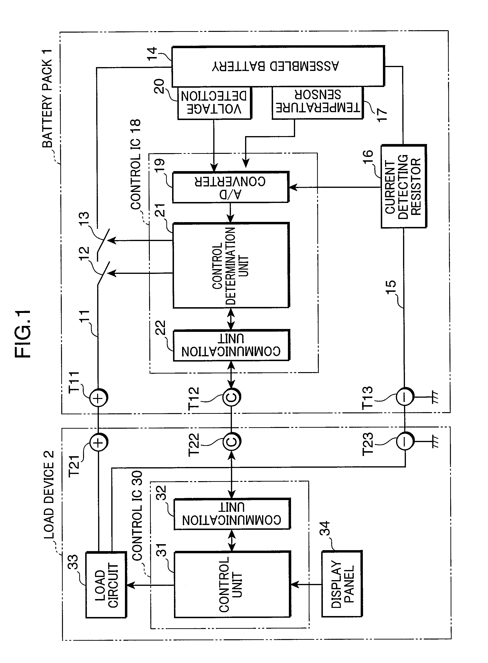
[0030]FIG. 1 is a block diagram showing an electronic structure of an electronic device system according to one embodiment of the present invention. In this electronic device system a battery pack 1 has a load device 2 supplied with power source from the battery pack 1, and the battery pack 1 is charged by a charger, which is not shown. When charging, the battery pack 1 is mounted on the load device 2 to charge the battery pack 1 via the load device 2. The battery pack 1 and the load device 2 are connected to each other by direct current high-side terminals T11, T21 for feeding power, communication signal terminals T12, T22, and GND terminals T13, T23 for power feeding and communication signals. The charger also is provided with the same three terminals.

[0031]In the battery pack 1, FET 12, 13 with different types of conductivity for charging and discharging are interposed in a direct current high-side charge / discharge path 11 extending from the terminal T11, and this charge / discharg...


PUM

PropertyMeasurementUnit
terminal voltageaaaaaaaaaa
discharging currentaaaaaaaaaa
voltage dropaaaaaaaaaa

Abstract

A battery internal short-circuit detection apparatus includes: a voltage detection unit for detecting a terminal voltage of the battery; a current detection unit for detecting a discharging current of the battery; a voltage drop and recovery detection unit for detecting a momentary voltage drop of the battery and a recovery from the voltage drop, in response to a result of detection performed by the voltage detection unit; and a determination unit for determining that an internal short circuit has occurred, when a maximum value of the discharging current detected by the current detection unit between the voltage drop and the recovery is equal to or lower than a threshold current.

Description

RELATED APPLICATIONS[0001]This application is the U.S. National Phase under 35 U.S.C. §371 of International Application No. PCT / JP2008 / 001412, filed on Jun. 4, 2008, which in turn claims the benefit of Japanese Application No. 2007-153926, filed on Jun. 11, 2007, the disclosures of which Applications are incorporated by reference herein.TECHNICAL FIELD[0002]The present invention relates to an apparatus and method for detecting an internal short circuit in a nonaqueous electrolyte secondary battery that has, between a negative electrode and a positive electrode thereof, a heat-resistant layer composed of a porous protective film or the like containing a resin binder and an inorganic oxide filler, a nonaqueous electrolyte olivine-type lithium iron phosphate secondary battery having an electrode plate resistance of not lower than 4 Ω·cm2, or other nonaqueous electrolyte secondary battery. The present invention also relates to a battery pack.BACKGROUND ART[0003]Patent Document 1 and Pat...

Claims


Application Information

Patent Timeline
Patent Type & Authority Patents(United States)
IPC IPC(8): G01N27/416H02J7/00H02J7/04
CPCG01R31/025H01M10/4235H01M10/48G01R31/36H01M2200/00H01M10/052G01R31/52Y02E60/10G01R31/392G01R31/3842G01R31/56G01R19/16542G01R19/30G01R19/12
Inventor ASAKURA, JUNNAKASHIMA, TAKUYANAKATSUJI, TOSHIYUKIFUJIKAWA, MASATO
Owner GK BRIDGE 1
Why Eureka
Try Eureka