Control apparatus of alternating-current motor

a technology of alternating-current motors and control apparatuses, which is applied in the direction of electric generator control, dynamo-electric converter control, dynamo-electric gear control, etc., can solve the problems of voltage loss, symmetry between positive and negative voltage applied to the motor, and large switching loss and conduction loss, so as to prevent torque pulsation and damage of the motor

Active Publication Date: 2013-01-01
AUTO TECH GRP LLC
View PDF24 Cites 19 Cited by
  • Summary
  • Abstract
  • Description
  • Claims
  • Application Information

AI Technical Summary

Benefits of technology

[0017]The above-mentioned configuration provides a control apparatus of an alternating-current motor, which performs driving in a synchronous pulse mode and in a one-pulse mode, capable of suppressing three-phase imbalance of motor current caused by an error from a true value contained in output of a position detector, an error of an inverter output voltage command, unevenness of on-voltage-drop among switching elements, or correlation variation of motor impedance, and capable of preventing torque pulsation and damage of the motor.

Problems solved by technology

Here, both of switching loss and conduction loss are large with such a high voltage resistant switching element.
Then, symmetry between positive and negative of the voltage applied to the motor (i.e., line voltage) is lost, so that noise and vibration is caused due to generation of electric vibration and torque pulsation with the motor.

Method used


Image

  • Control apparatus of alternating-current motor
  • Control apparatus of alternating-current motor
  • Control apparatus of alternating-current motor

Examples


first embodiment

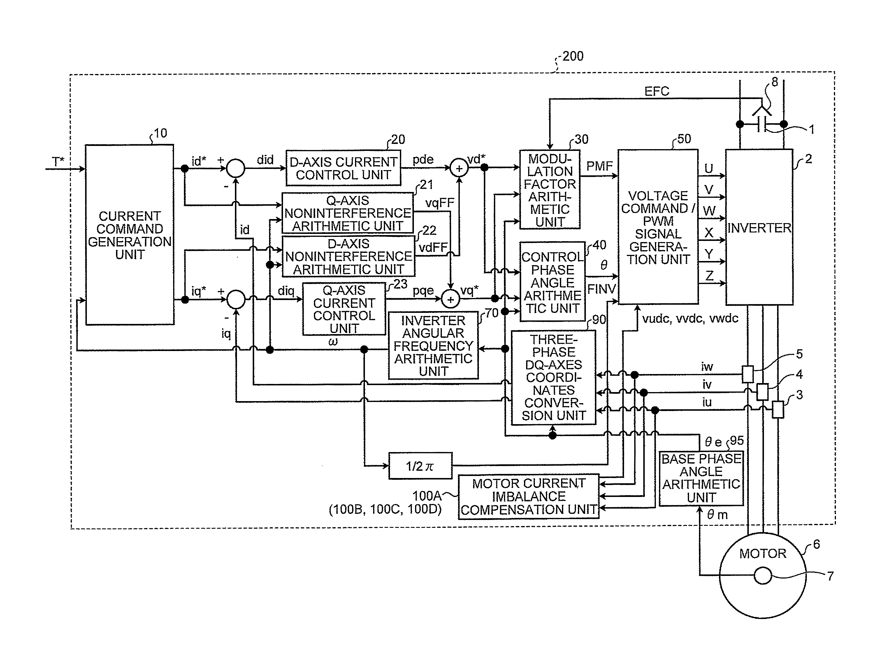
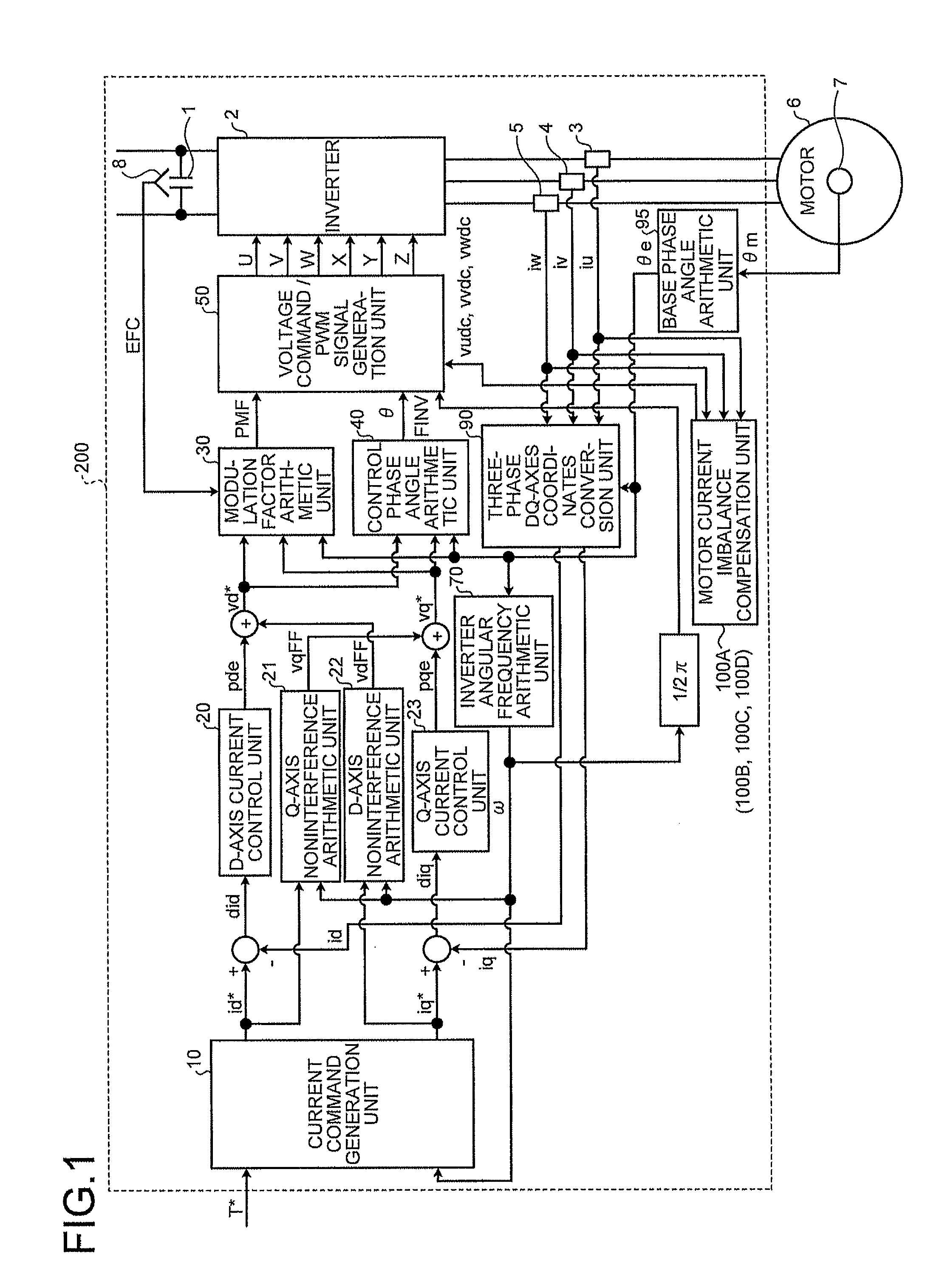
[0028]FIG. 1 is a view illustrating a structural example of a control apparatus of an alternating-current motor according to a first embodiment of the invention. As illustrated in FIG. 1, a main circuit is configured with a capacitor 1 being a direct-current source, an inverter 2 converting direct-current voltage of the capacitor 1 into alternating-current voltage of an arbitrary frequency, and a permanent magnet synchronous motor (hereinafter, simply called a motor) 6. The circuit is provided with a voltage detector 8 to detect voltage of the capacitor 1, and current detectors 3, 4, 5 to respectively detect motor currents iu, iv, iw being output line currents of the inverter 2. The motor 6 is provided with a resolver 7 being a position detector to detect a rotor mechanical angle θm. The detection signals are inputted respectively to units which are described later.

[0029]Here, it is also possible that an encoder is used instead of the resolver 7. Further, it is also possible to adop...

second embodiment

[0057]FIG. 5 is a view illustrating a structural example of the motor current imbalance compensation unit 100B according to the second embodiment of the invention. Since the second embodiment is based on the first embodiment, only the parts different from the configuration of the first embodiment will be described in the following, while description for the parts having the same configuration as the first embodiment will not be repeated. Compared to the first embodiment, as illustrated in FIG. 5, the currents iu, iv of two phases among the three-phase currents iu, iv, iw detected respectively by the current detectors 3, 4, 5 are inputted to the motor current imbalance compensation unit 100B. Then, the unnecessary frequency components are eliminated respectively by the LPFs 101U, 101V. Further, after the polarity is inverted respectively by the gains 102U, 102V, inputting to the proportional integral elements 103U, 103V is performed. The outputs of the proportional integral elements ...

third embodiment

[0060]Next, the configuration of a third embodiment of the invention will be described. Since the third embodiment is based on the first embodiment, only the parts different from the configuration of the first embodiment will be described in the following, while description for the parts having the same configuration as the first embodiment will not be repeated. FIG. 6 is a view illustrating a structural example of the motor current imbalance compensation unit 100C according to the third embodiment of the invention. Compared to the first embodiment, as illustrated in FIG. 6, the currents iu, iv of two phases among the three-phase currents iu, iv, iw detected respectively by the current detectors 3, 4, 5, which are inputted to the motor current imbalance compensation unit 100C. Then, the unnecessary components are eliminated, respectively, by the LPFs 101U, 101V. Further, after the polarity is inverted respectively by the gains 102U, 102V, inputting to the proportional integral eleme...


PUM


Abstract

A control apparatus of an alternating-current motor includes an inverter which is connected to a direct-current source and outputs three-phase alternating currents to the alternating-current motor, a current detector which detects a current of the alternating-current motor, a voltage command / PWM signal generation unit which calculates an output voltage command of the inverter based on a signal from the current detector and generates a pulse width modulation signal to control a switching element arranged in the inverter based on the output voltage command, and a motor current imbalance compensation unit which generates a motor current imbalance compensation amount based on the current detected by the current detector. The pulse width modulation signal is directly or indirectly adjusted at the voltage command / PWM signal generation unit based on the motor current imbalance compensation amount in accordance with a driving state of the inverter.

Description

TECHNICAL FIELD[0001]The invention relates to a control apparatus of an alternating-current motor for an electric vehicle driving, and particularly, relates to a control apparatus suitable for control of a permanent magnet synchronous motor.BACKGROUND ART[0002]In recent years, in application fields of alternating-current motors such as industrial equipment, home appliances and automobiles, a method to control driving of a permanent magnet synchronous motor with an inverter is becoming popular instead of a method to control driving of an induction motor in the related art with an inverter. A permanent magnet synchronous motor is known as a high efficiency motor compared to an induction motor because of the following features. Since magnetic flux is established by a permanent magnet incorporated in a rotor, current corresponding to excitation current is unnecessary. Since current does not flow through the rotor, secondary copper loss is not generated. Torque is effectively obtained by...

Claims


Application Information

Patent Timeline
Patent Type & Authority Patents(United States)
IPC IPC(8): H02P27/04H02P21/00H02P6/06H02P6/08H02P21/22H02P25/022H02P25/026H02P27/06H02P27/08
CPCH02P21/0035H02P27/04H02P21/06H02P21/22H02P21/00B60L15/08
Inventor KITANAKA, HIDETOSHI
Owner AUTO TECH GRP LLC
Why Eureka
Try Eureka