Fracture-resistant helical stent incorporating bistable cells and methods of use

a helical stent, bistable technology, applied in the field of vascular prostheses, can solve the problems of plastically deformable stents, stents that are not suitable for blood vessels, plastically deformable stents, and rapid work hardening and fracture when subjected to multiple bending cycles

Inactive Publication Date: 2013-01-15
CELONOVA STENT
View PDF136 Cites 32 Cited by
  • Summary
  • Abstract
  • Description
  • Claims
  • Application Information

AI Technical Summary

Benefits of technology

[0023]In view of the foregoing drawbacks of previously-know vascular prostheses, it is an object of the present invention to provide a vascular prosthesis that may be used in blood vessels subject to axial and torsional loading, and which is not prone to migration.
[0024]It also is an object of this invention to provide a vascular prosthesis capable of withstanding high compressive loads without experiencing significant radial strains, thereby avoiding the potential for the axial migration when the compressive loads are accompanied by vessel length changes.
[0025]It is a further object of the present invention to provide a vascular prosthesis having high radial strength, and which is capable of bending along its length with a high degree of resistance to bending fatigue once deployed in a body vessel.

Problems solved by technology

Although such stents have proved adequate for treating occlusive disease of the cardiac vessels, they are subject to a number of well-documented drawbacks when used outside the cardiac vasculature.
For example, previously known plastically deformable stents generally are not appropriate for blood vessels that are subject to compressive or other forms of dynamic loading, such as the arteries in the extremities or the carotid arteries.
Thus, plastically deformable stents should not be employed in vessels that routinely experience longitudinal shape changes, because the stents lack flexibility to conform to the vessel, and may fracture, deform or cause dissection of the vessel.
Although the links are capable of undergoing a limited amount of bending strain during initial deployment, they will quickly work-harden and fracture when subjected to multiple bending cycles, e.g., in a peripheral vessel that is subject to bending.
Additionally, because plastically deformable stents have very little resilience, the stents of the foregoing patents are not suitable for use in vessels that are subject to high radially compressive forces, such as the carotid arteries.
Because the carotid arteries lie relatively close to the surface of the neck, there is a substantial risk that the stent may be inadvertently crushed by a blow or other pressure to the neck.
Self-expanding wire mesh tubes of the type described in the above patent to Wallsten, and coiled sheet tubes as described in the above patent to Kreamer, provide a high degree of crush resistance, but only limited capability to flex longitudinally or sustain axial compressive loads.
Self-expanding ring structures, such as described in the above patent to Gianturco, also provide good crush radial crush resistance, but do not provide high radial strength, and are subject to migration if subjected to cyclic compression.
However, even self-expanding helical stents are not expected to perform adequately when subjected to cyclic axially compressive and / or torsional loading, such as encountered in the superficial femoral arteries (“SFA”).
Patients suffering from diseases that occlude these vessels, such as arteriosclerosis and vascular complications of diabetes, often may suffer reduced mobility and in extreme cases, may require amputation.
Consequently, previously known self-expanding helical stents are not expected to perform satisfactorily when deployed in the SFAs and other vessels that experience cyclic axial and / or torsional loading.
In addition to the lack of a suitable prosthesis design for stenting the SFAs and similar vessels, interventional procedures involving such arteries pose other difficulties, particularly with respect to sizing and placement of stents in those vessels.
While the latter two methods provide excellent views of the vessel topography, this information typically is static, pre-procedure information, rather than real-time.
Often, the use of contrast agents provides less than ideal precision, for example, because the contrast agent tends to disperse once introduced into the bloodstream.
In addition, where the vessel is highly occluded, there may be very little flow and thus difficult to assess the size and severity of the occlusion.

Method used


Image

  • Fracture-resistant helical stent incorporating bistable cells and methods of use
  • Fracture-resistant helical stent incorporating bistable cells and methods of use
  • Fracture-resistant helical stent incorporating bistable cells and methods of use

Examples


Embodiment Construction

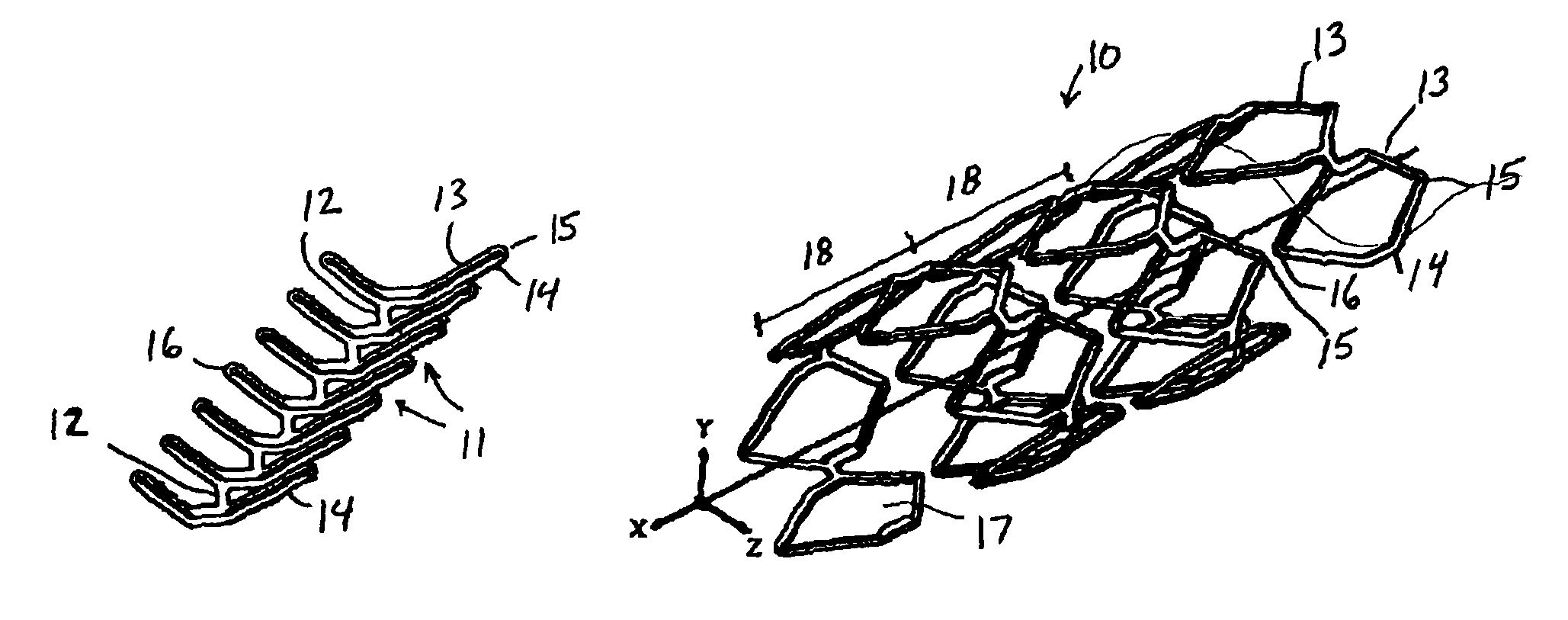
[0045]The present invention is directed to a vascular prosthesis having a helical configuration and formed of a plurality of bistable cells. The bistable mode of operation of the vascular prosthesis (hereinafter also referred to as a “stent”) of the present invention combines the superior fatigue resistance of previously known self-expanding helical stents with the superior resistance to radial compressive forces and positive fixation characteristics of previously known plastically deformable stents. The result is a vascular prosthesis having high radial strength, improved resistance to fatigue fracture and low potential for migration.

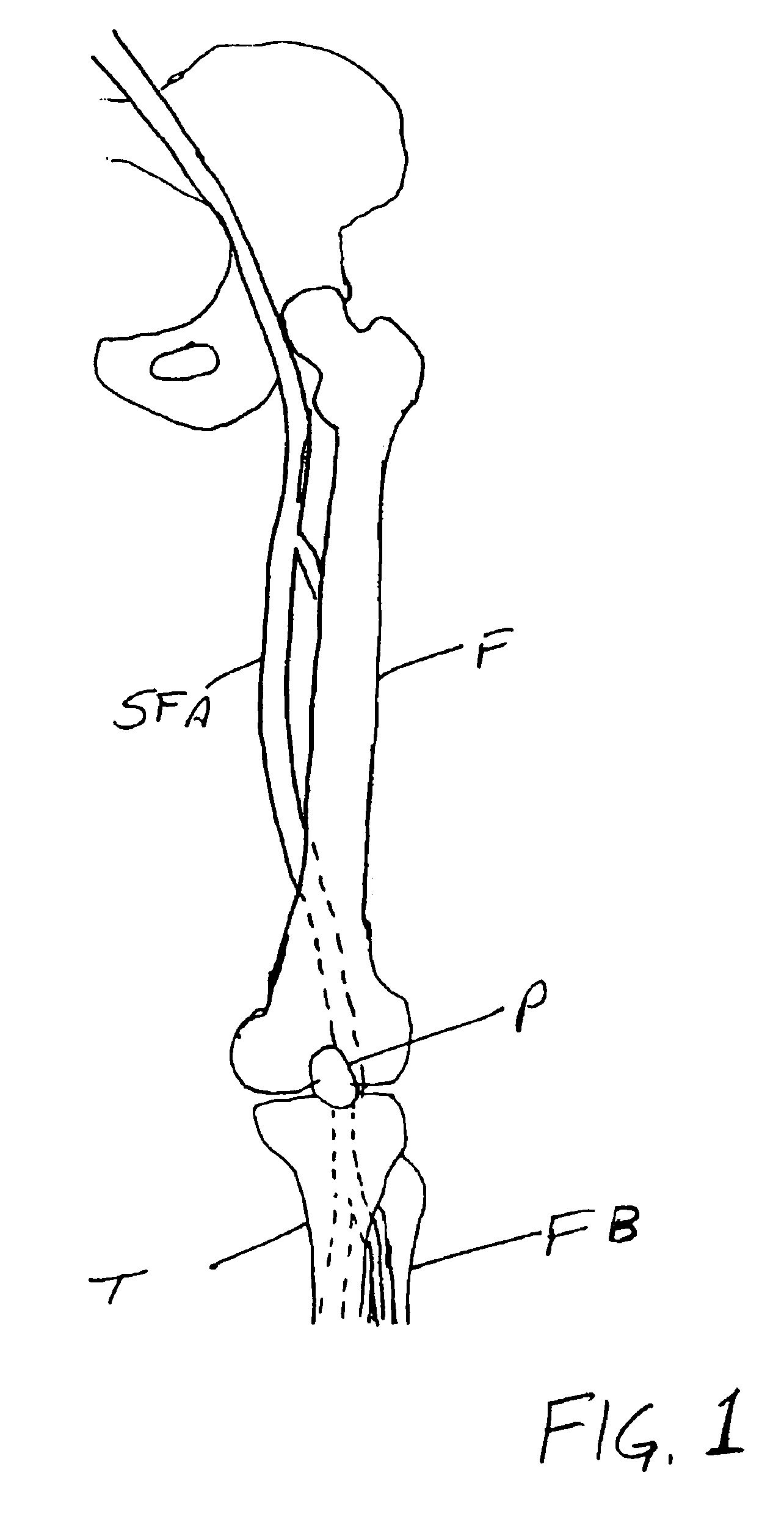
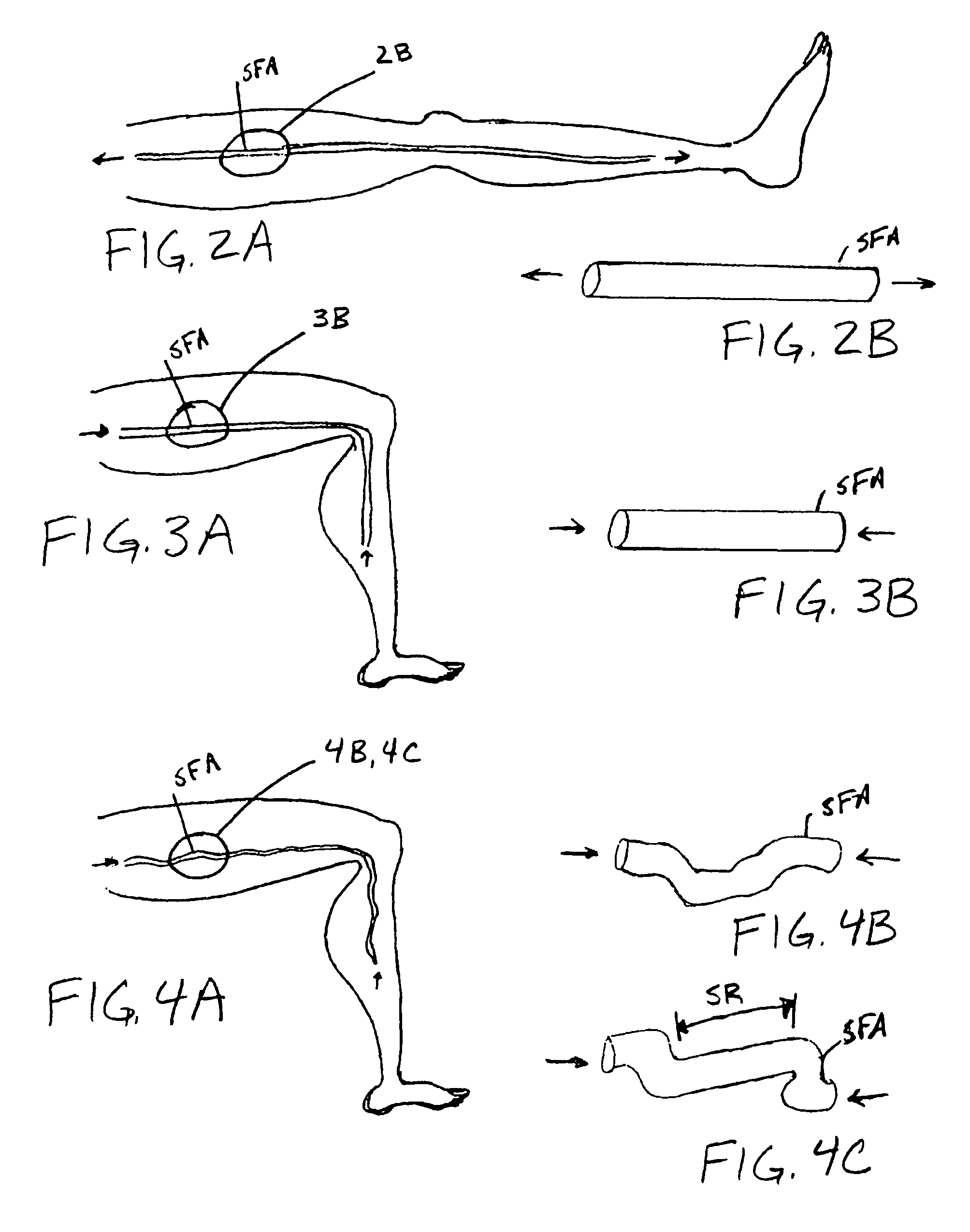
[0046]The vascular prosthesis of the present invention is expected to be especially advantageous when deployed in blood vessels subject to dynamic loading, such as the superficial femoral artery. Attempts to use self-expanding helical stents and plastically deformable stents in such vessels often resulted in stent failure, due either to fatigue fractur...


PUM


Abstract

Vascular prostheses and methods of use are provided, wherein the vascular prosthesis includes a plurality of bistable unit cells configured to form a helical structure. A visualization catheter also is provided for use ensuring accurate measurement of a lesion and ensuring delivery and placement of the vascular prosthesis.

Description

REFERENCE TO RELATED APPLICATIONS[0001]The present application is a continuation-in-part of U.S. patent application Ser. No. 10 / 270,771, filed Oct. 11, 2002, which is a continuation of U.S. patent application Ser. No. 09 / 012,843, filed Jan. 23, 1998, now U.S. Pat. No. 6,488,702, which claims the benefit of priority of U.S. provisional application Ser. No. 60 / 036,359, filed Jan. 24, 1997.FIELD OF THE INVENTION[0002]The present invention relates to vascular prostheses, and in particular to vascular prostheses for use in vessels that are subject to cyclic axial or torsional loading, such as may occur in the superficial femoral arteries. In particular, the present invention relates to vascular prostheses comprising a plurality of helically arranged bistable cells.BACKGROUND OF THE INVENTION[0003]Vascular prostheses, commonly referred to as “stents,” are now widely used in interventional procedures for treating lesions of the coronary arteries and other vessels. Such devices generally ha...

Claims


Application Information

Patent Timeline
Patent Type & Authority Patents(United States)
IPC IPC(8): A61F2/06A61B17/11A61F2/00
CPCA61B17/11A61F2/064A61F2/91A61F2/915A61F2/88A61F2002/91541A61F2/07A61F2/06A61M25/01A61L27/04
Inventor BESSELINK, PETRUS ANTONIUSBATES, MARK C.
Owner CELONOVA STENT
Why Eureka
Try Eureka