Resilient flying lead and terminus for disk drive suspension

a flying lead and disk drive technology, applied in the direction of instruments, support for heads, record information storage, etc., can solve the problems of slider performance dependent on a good grounding, degraded approach, and poor electrical connection quality, so as to improve the electrical grounding of the slider and achieve optimal performance of the hard disk drive slider. , the effect of improving the electrical connection

Active Publication Date: 2013-03-12
MAGNECOMP
View PDF31 Cites 34 Cited by
  • Summary
  • Abstract
  • Description
  • Claims
  • Application Information

AI Technical Summary

Benefits of technology

[0017]In one aspect of the invention, an additive manufacturing method is provided to connect the copper circuitry of a component such as a slider with the stainless steel part of the suspension interconnect using vias modified in manufacture to have better electrical connection than available heretofore. In one aspect, the invention provides optimal performance in hard disk drive sliders by improving the electrical grounding thereof through a via having a copper conductor bonded to a stainless steel layer using a tie layer of chromium and optionally a copper flash layer as well.

Problems solved by technology

One of the major challenges in the design of hard disk drive suspensions is attaining a suitable, reliable grounding connection between the conductive copper traces connected electrically to the slider and the underlying stainless steel foil layer given the limited space available to make the connection.
The difficulty of bonding to stainless steel and dissimilarity of the metals (Cu, Au, SST) pose additional significant challenges to creating a reliable grounding of the slider, but reliable grounding is essential to maintaining the signal fidelity between the read / write head and amplifier.
This approach is deficient, however, since conductive adhesive connections are typified by very high interconnect resistance resultant from the passive (self-healing) nature of the stainless steel and the lack of a conductive, fully metallic bond between the steel layer and the conductive adhesive.
High interconnect resistance limits the quality of the electrical connection to ground and thus slider performance dependent on a good grounding is degraded.
Spanning leads are very fragile and can be easily mis-bent during manufacture causing lowered manufacturing yields.
Further, even if perfectly accomplished, the process of physically bending and adhering leads to the stainless steel suspensions is a very labor-intensive process that does not lend itself to high-volume, low-cost manufacturing, such as simultaneous gang bonding of multiple suspensions.
In both of these prior art processes the presence of conductive adhesives can cause increased drive contamination that may adversely affect drive reliability, and their use is environmentally undesirable for workers.
The flying leads therefore lack the stiffness provided by the underlying dielectric layer.
The fragile unsupported lead is prone to damage during assembly, test, or when separating the ultrasonic or solder terminal of this terminus for rework.
In recent years, as the thickness of the copper conductor layer has decreased from about 12 μm to about 7 μm in the last few years, the lead has become even more fragile, making rework even more difficult.
An unintended drawback to increasing the toughness of the copper conductor by substituting a stronger copper alloy for use in the suspension signal traces, is that doing so undesirably increases the gimbal stiffness, whereas decreased gimbal stiffness is desired for the emerging smaller read / write heads.
This is particularly problematic in the case of a copper conductor upon an inert steel, as the presence of the inherent passive amorphous oxide which inherently forms on stainless steel is not readily receptive to acceptable adhesion of subsequent metal deposition.

Method used


Image

  • Resilient flying lead and terminus for disk drive suspension
  • Resilient flying lead and terminus for disk drive suspension
  • Resilient flying lead and terminus for disk drive suspension

Examples


Embodiment Construction

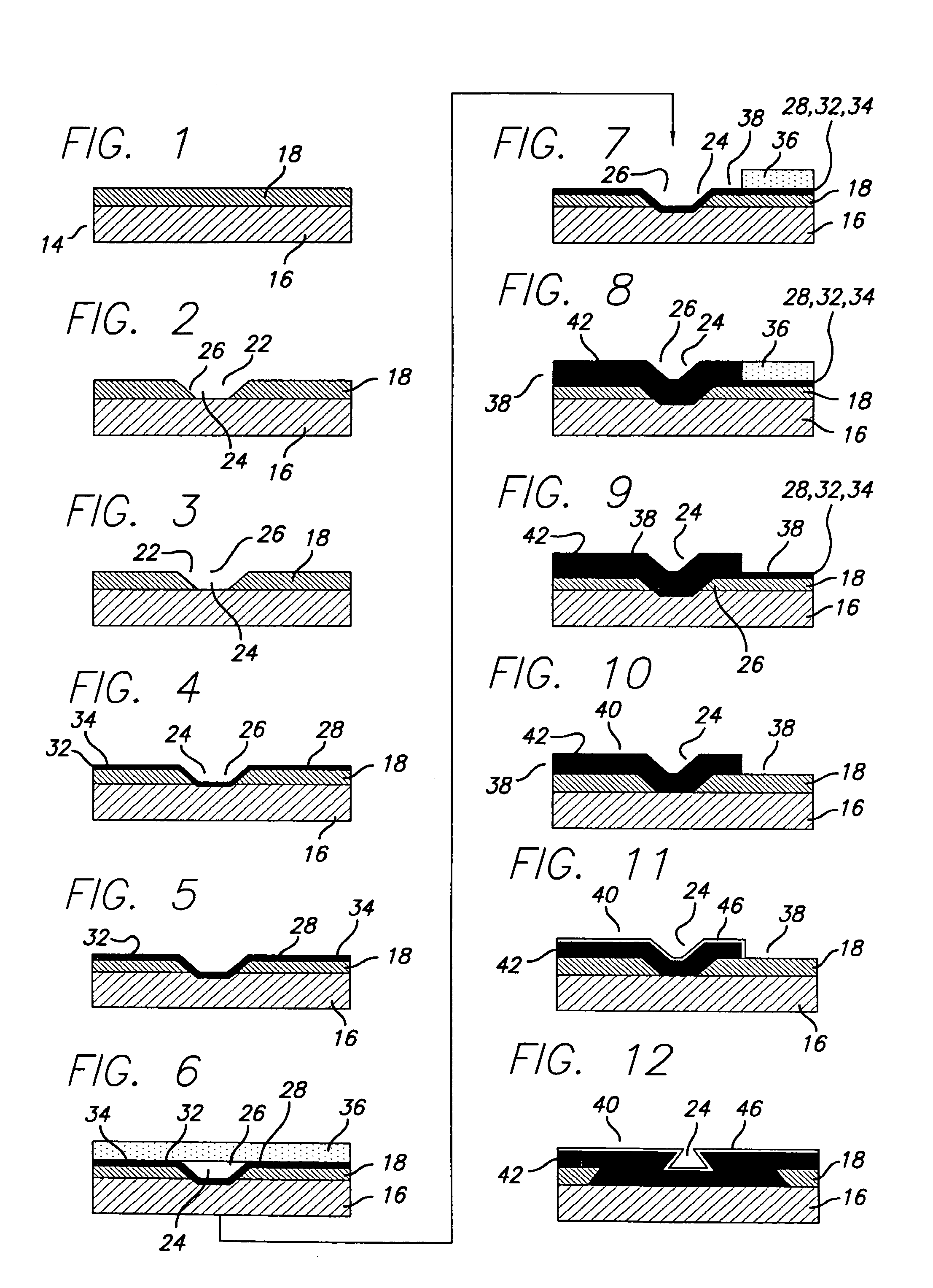
[0038]The invention provides a simpler and more economical solution than those criticized above for manufacturing suspension interconnects having a reliable electrical connection between the circuit components to be grounded and the grounding layer of a stainless steel foil by creating a metallized via between them. It is well known that there are inherent difficulties in making electrical connections to stainless steel. In the invention, however, these difficulties are avoided or obviated by using a sputtered tie layer such as chromium that can be used to attach a conductor, e.g. copper, attached to a component, e.g. a slider, to a ground such as stainless steel. FIGS. 1-11 show the invention process flow for creating a metal via between the copper circuit and stainless steel layers on a hard disk drive suspension interconnect. FIGS. 15-27 show the invention process flow for creating a metal via between the copper circuit and stainless steel coated with conductive copper layer.

[003...


PUM

PropertyMeasurementUnit
thicknessaaaaaaaaaa
thicknessaaaaaaaaaa
thicknessaaaaaaaaaa

Abstract

A disk drive suspension circuit has copper signal conductors connected by vias through an insulative layer to respective stainless steel flying leads. The stainless steel flying leads are activated and plated with one or more metals, with a final layer over the flying lead being a layer such as gold, suitable for bonding to form bond pads. The gold bond pads may be attached using thermosonic welding, solder ball bonding, or other suitable methods to an electrical component such as wires or a the disk drive's pre-amp circuit.

Description

CROSS-REFERENCE TO RELATED APPLICATIONS[0001]This application is a continuation in part of U.S. patent application Ser. No. 11 / 485,912 filed Jul. 13, 2006, which is a continuation in part of U.S. application Ser. No. 11 / 340,298 filed Jan. 26, 2006, which application claims the benefit of U.S. Provisional Application Ser. No. 60 / 715,854, filed Sep. 9, 2005, the disclosures of which are incorporated as if fully set forth herein.BACKGROUND OF THE INVENTION[0002]1. Field of the Invention[0003]This invention relates to disk drive suspensions, and more particularly, to improvements in the manufacture of disk drive suspension interconnects to secure better electrical grounding of suspension components such as copper circuit layers to grounded portions of the suspension such as stainless steel layers including stainless steel layers per se and copper metallized stainless steel layers, to enable increased numbers of copper circuit layers, and further relates to suspension products thus manuf...

Claims


Application Information

Patent Timeline
Patent Type & Authority Patents(United States)
IPC IPC(8): G11B5/48
CPCG11B5/486H05K3/44H05K1/056H05K3/388H05K2201/0347H05K2201/09554H05K2201/09827B33Y80/00G11B5/48
Inventor SCHREIBER, CHRISTOPHERDUNN, CHRISTOPHER
Owner MAGNECOMP
Why Eureka
Try Eureka