Petrol engine having a low-pressure EGR circuit

a low-pressure egr circuit and engine technology, applied in the direction of position/direction control, non-fuel substance addition to fuel, exhaust gas recirculation, etc., can solve the problems of increasing the consumption of gasoline, affecting the combustion efficiency of the engine, and affecting the combustion efficiency of the air-gasoline mixture. , to achieve the effect of limiting the occurrence of knocking in the gasoline engin

Active Publication Date: 2013-04-02
VALEO SYST DE CONTROLE MOTEUR
View PDF13 Cites 5 Cited by
  • Summary
  • Abstract
  • Description
  • Claims
  • Application Information

AI Technical Summary

Benefits of technology

[0006]The exhaust gas recirculation circuit makes it possible to introduce, into the supply system, cooled exhaust gases which it has been found made it possible to delay the occurrence of knocking. Specifically, the cooled exhaust gases thus reintroduced play no role in the combustion but take on a function as a heat trap notably making it possible to limit the occurrence of areas of spontaneous combustion in the mixture contained in the combustion chamber. Therefore, introducing exhaust gas into the combustion chamber makes it possible to increase knocking resistance and therefore to increase the ignition advance. The result of this is an increase in engine torque for one and the same richness in fuel relative to a conventional gasoline engine, or to reduce the mixture to stoichiometric proportions and reduce fuel consumption for performances that are identical to those of conventional gasoline engines. Moreover, this also makes it possible to reduce the temperature of the exhaust gases and to limit the impact of the latter on the components of the exhaust system such as the turbine and the catalytic converter. At low load, the introduction into the combustion chamber of exhaust gas therefore makes it possible to reduce the nitrogen oxide emissions (the production of the catalytic converter then requires a smaller quantity of precious metals) and to reduce pumping losses at the intake (thereby reducing fuel consumption). Tapping off the gases downstream of the turbine appears particularly effective in obtaining the desired effects.
[0008]A water cooler (also called an air-water heater) is particularly effective and makes it possible, with a relatively small footprint, to sufficiently cool the recirculated air-gas mixture which comes out of the compressor at a high temperature of the order of 180° C. This limited footprint of the water cooler also makes it possible to bring the point of injection of the recirculated gases closer to the engine block. This makes it possible to improve the response of the engine to variations of speed.
[0009]A further subject of the invention is a method for managing such an engine comprising the step, when the motor has an operating parameter reaching a limit threshold at which knocking occurs, of acting on a quantity of gas from the recirculation circuit introduced into the supply system. This makes it possible to make the air pressure less sensitive to knocking.
[0011]The ignition advance makes it possible to have better combustion producing greater torque partly compensating for the torque reduction caused by the introduction of the cooled exhaust gases. The ignition advance can also be maintained at its former level or even reduced and the richness of the mixture modified in consequence as a function of the quantity of exhaust gas reintroduced.

Problems solved by technology

When the engine is on full load, for example in the acceleration phase, it happens that the combustion of the air-gasoline mixture is not perfect, the compression of the mixture generating, in the combustion chamber, shock waves (explosive combustion or knocking) that could damage the engine.
This has the drawbacks of increasing the consumption of gasoline and, departing from the stoichiometric proportions allowing complete combustion of the air-gasoline mixture, of reducing the efficiency of the catalytic converter of the exhaust system which operates optimally when the stoichiometric proportions are maintained.
The result of this is increased pollution.

Method used


Image

  • Petrol engine having a low-pressure EGR circuit
  • Petrol engine having a low-pressure EGR circuit

Examples


Embodiment Construction

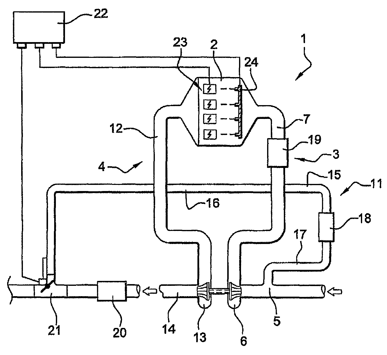
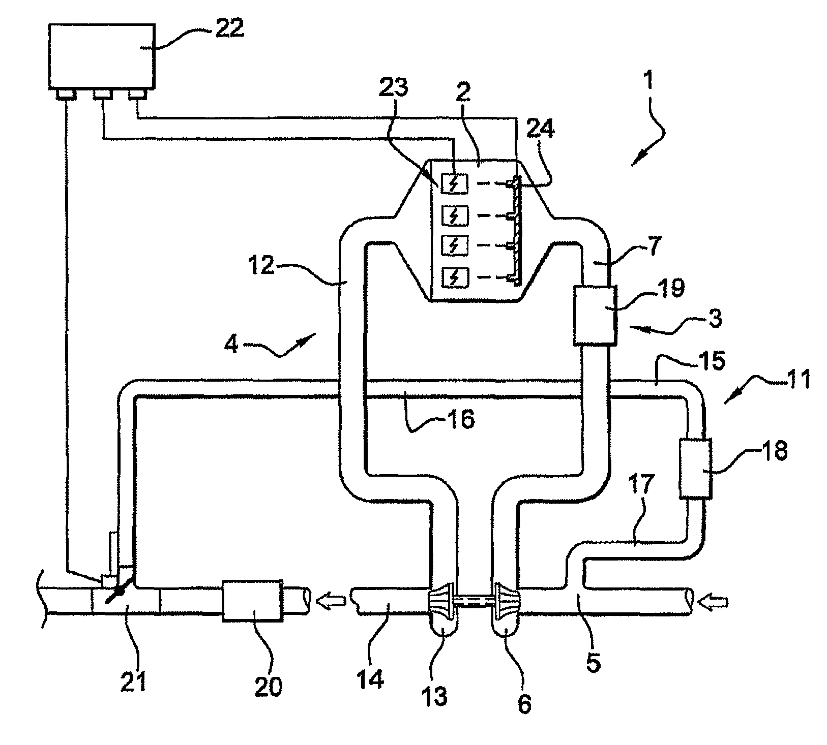
[0014]With reference to the figure, the heat engine according to the invention, generally designated as 1, comprises an engine block 2 defining, in a manner known per se, combustion chambers provided with pistons rotating an output shaft of the engine. The combustion chambers of the engine block 2 are connected in a manner known per se to a supply system generally designated as 3 and to an exhaust system generally designated as 4.

[0015]The supply circuit 3 comprises an intake duct 5 leading into a compressor 6 connected to a supercharging air cooler itself connected via an intake manifold 7 to the combustion chambers of the engine block 2. The compressor 6 is in this instance a centrifugal compressor known per se comprising a bladed rotor 8 mounted so as to pivot about a shaft 9 in a housing 10. The intake duct 5 leads into the housing 10 coaxially with the rotation shaft 9.

[0016]The exhaust system 4 is known per se and comprises an exhaust manifold 12 connecting the combustion cham...


PUM


Abstract

Internal combustion petrol engine comprising an engine block (2) connected to an intake circuit (3) including a compressor (6) and an exhaust circuit (4) including a turbine (13) which drives the compressor, the internal combustion engine including an exhaust gas recirculation circuit (11) which is connected to the exhaust circuit downstream of the turbine and is connected to the intake circuit upstream of the compressor, the recirculation circuit comprising a cooler. Method of managing such an engine.

Description

[0001]The present invention relates to a heat engine that can be used notably for moving a motor vehicle and a method for managing such an engine. The invention more particularly relates to turbocharged engines using gasoline as fuel.BACKGROUND OF THE INVENTION[0002]Such an engine usually comprises an engine block which delimits combustion chambers connected to an intake circuit comprising a compressor and an exhaust system comprising a turbine for driving the compressor. The engine block is associated with a device for introducing gasoline into the combustion chambers, usually injectors, and with an ignition device in order to initiate, in each combustion chamber, the combustion of the mixture formed by the air from the intake circuit and by the gasoline from the injectors. When the engine is on full load, for example in the acceleration phase, it happens that the combustion of the air-gasoline mixture is not perfect, the compression of the mixture generating, in the combustion cha...

Claims


Application Information

Patent Timeline
Patent Type & Authority Patents(United States)
IPC IPC(8): F02B47/08
CPCF02D35/027F02D41/005F02M25/0709F02D37/02F02D41/0007Y02T10/47F02M26/06Y02T10/40
Inventor LUTZ, PHILIPPEPOTTEAU, SEBASTIENALBERT, LAURENT
Owner VALEO SYST DE CONTROLE MOTEUR
Why Eureka
Try Eureka