Splice system for connecting rebars in concrete assemblies

a technology of splicing system and concrete assembly, which is applied in the direction of couplings, manufacturing tools, mechanical equipment, etc., can solve the problems of deteriorating structure strength, many concrete structures that cannot be connected in a safe and efficient manner, and many concrete structures that cannot be constructed. , to achieve the effect of high corrosive environmen

Active Publication Date: 2013-04-09
WISCONSIN ALUMNI RES FOUND
View PDF32 Cites 28 Cited by
  • Summary
  • Abstract
  • Description
  • Claims
  • Application Information

AI Technical Summary

Benefits of technology

[0008]The present invention provides a corrosion resistant rebar splice system that is suitable for connecting multiple rebars, including steel or other metallic rebars, fiber-reinforced polymer rebars, and / or other rebars, to each other. In one embodiment, the system includes a non-metallic, e.g., polymeric tube, which extends over adjacent ends of aligned rebars. The polymeric tube may then be filled with cement grout, locking the grout and polymeric tube and rebars to each other. This provides a rebar system made at least partially from non-metallic, corrosion-resistant materials so that the rebar system can be used for reinforcing concrete while having a relatively long use life in highly corrosive environments. In some implementations, providing fiber-reinforced polymer rebars and splice joint connecting components that are made from substantially similar materials allows the various components of a polymer rebar system to, e.g., thermally expand or contract at substantially similar rates. In other implementations, the polymeric tubes are used to connect steel rebars without requiring users to manipulate heavy cast iron or other metallic splice couplers.
[0009]In a further embodiment, the splice joint at and within the polymeric tube has a tensile strength, an ultimate capacity, and an ultimate stress capacity that are at least as great as a piece of metallic rebars or fiber-reinforced polymer rebar alone. This allows the splice joint to be a relatively strong component within a rebar system used for reinforcing concrete.
[0012]Thus, it is an object of at least one embodiment of the invention to provide a splice system having a splice tube assembly with a polymeric tube that accepts ends of rebars and a volume of grout therein, defining an embedment length that is sufficiently large in magnitude when compared to a diameter of the rebar, providing a suitably large bonding surface area between the rebar and grout. By providing a sufficiently large embedment length and thus also a sufficiently large bonding surface area, instances of non-desired withdrawals of the rebar(s) from the tube, e.g., slip-type failures, can be reduced.
[0014]It is thus an object of at least one embodiment of the invention to provide a splice tube assembly with polymeric tube having internal locking structures. By providing interface structures within the tube for the grout to interlock with and / or into the grout remains longitudinally fixed within the tube, whereby the grout can serve at least partially as a force transfer medium, locking the rebars together and transmitting various forces therebetween, and thus allowing multiple sections of rebar to be connected lengthwise for joining multiple precast concrete structures.
[0015]In a yet further embodiment, the reinforcing layer reduces tendencies of radial expansion of the grout when the splice tube assembly is pulled in tension. Furthermore, the reinforcing layer can reduce tendencies of radial expansion of the polymeric tube that can be induced by changing temperatures of the splice tube assembly. The reinforcing layer may be a composite having a reinforcing material component and a resin or adhesive components. The reinforcing material components can be made of, e.g., glass and / or carbon fiber and can be configured as a fibrous strand(s) or a sheet-like mat made from such material(s). The reinforcing material component can be wound or applied in a single layer or multiple layers over the outer circumferential surface of the polymeric tube aligned in the same direction or in differing directions and crisscrossing or cross-wrapping each other.
[0016]It is thus another object of at least one embodiment to hold dimensions of a splice tube assembly relatively constant by confining the polymeric tube within a reinforcing layer that mitigates radial expansion of the tube. By restricting the polymeric tube's ability to radially expand, the splice tube assembly is less likely to damage its grout due to differing rates of expansion of the differing materials, thereby maintaining the integrity of the splice joint.

Problems solved by technology

Without the added tensile strength provided by the rebars, many concrete structures would not be possible.
The significant disadvantage of precast concrete structures is in how to connect the precast members in a safe and efficient manner.
These connections are susceptible to corrosion which could lead to deterioration of the strength of the structure.
The primary cause of corrosion in steel joint connects is exposure to sodium chloride that is present in marine environments or de-icing salts that are applied to bridge decks and parking structures.
However, steel connectors, like cast-iron rebar connectors and all other metallic rebar connectors, can be rather heavy and bulky.
This can, at times, prove tiring and frustrating for the workers that handle the metallic connectors.
Additionally, at least some metallic connectors require complex casting and finish machining procedures for their production, which can render the metallic connectors relatively costly.
Despite best efforts, however, such fiber-reinforced polymer rebars have only been implemented in pre-cast concrete construction practices to a modest extent.
A primary reason for the lack of implementation of fiber-reinforced polymer rebars in pre-cast concrete construction practices is that splicing or connecting multiple fiber-reinforced polymer rebars in such applications has proven frustrating or impractical.
Welding is unfeasible, rebar overlap can require large overlapping segments which may be wasteful, and cast-iron connectors remain susceptible to corrosion in spite of the corrosion resistant qualities of the fiber-reinforced polymer rebars which frustrates many of the most desirable characteristics of the fiber-reinforced polymer rebars.

Method used


Image

  • Splice system for connecting rebars in concrete assemblies
  • Splice system for connecting rebars in concrete assemblies
  • Splice system for connecting rebars in concrete assemblies

Examples


Embodiment Construction

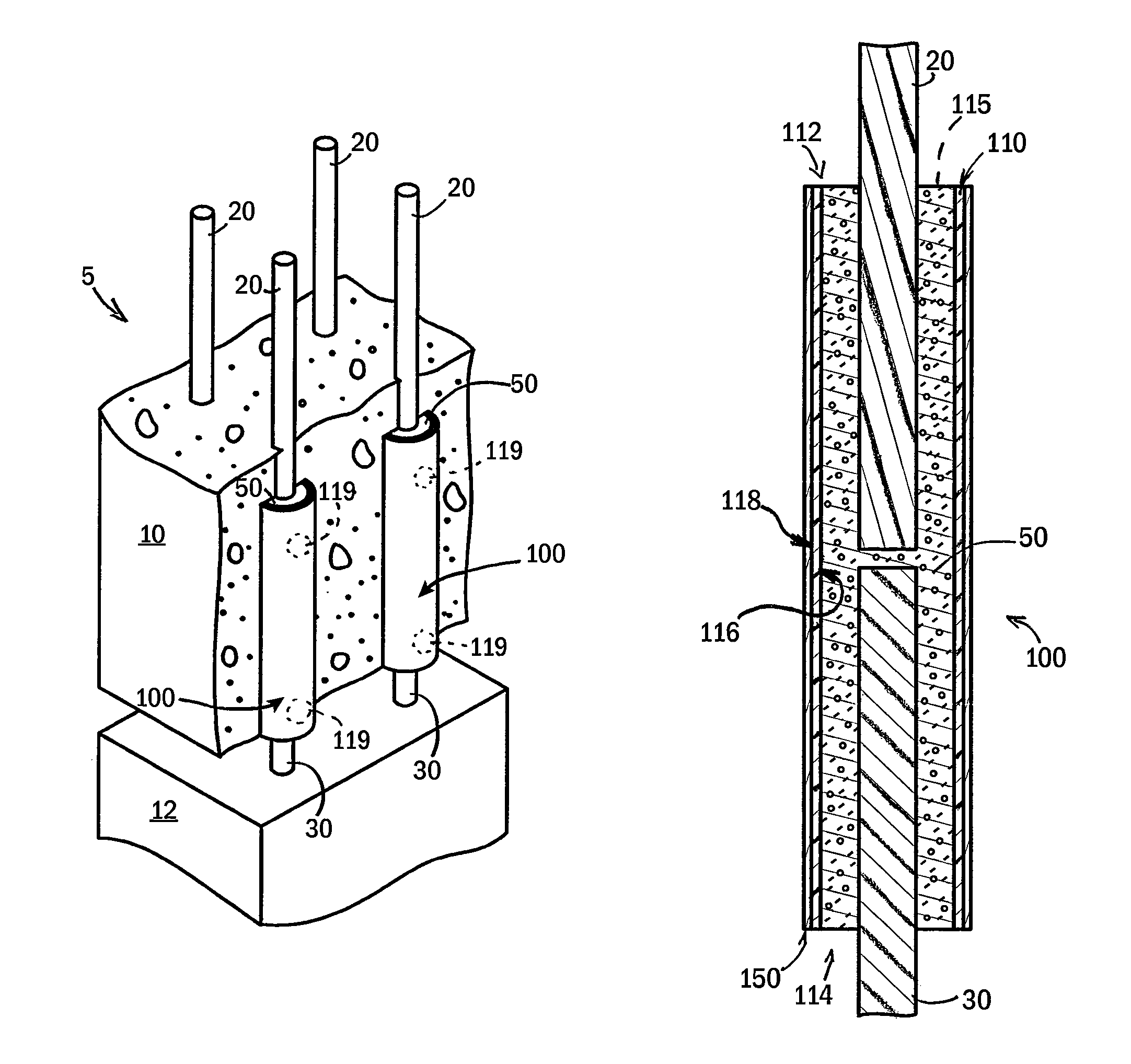
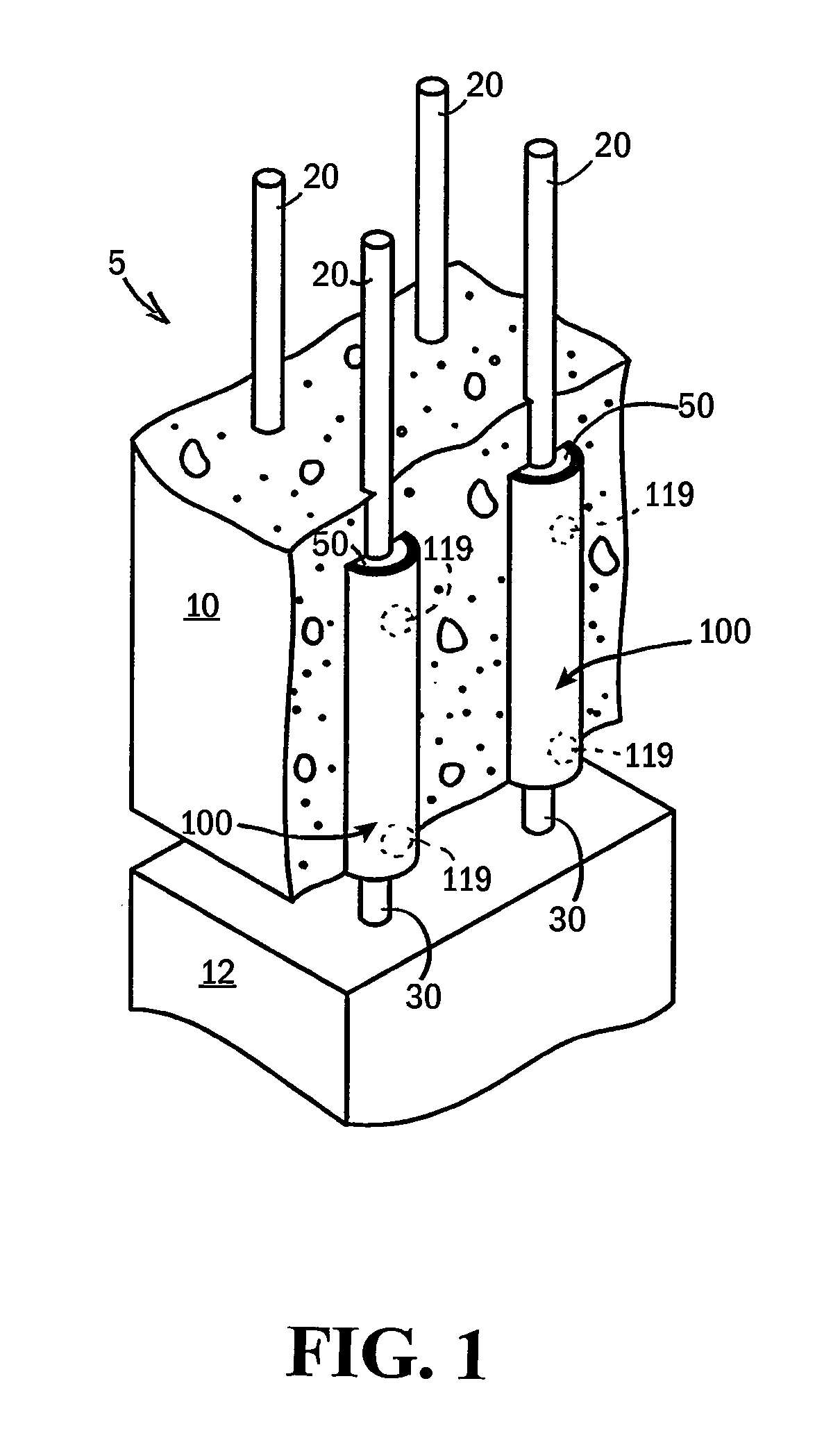
[0023]Referring now to FIG. 1, the present invention provides a splice system for connecting metallic rebars or fiber-reinforced polymer rebars, e.g., system 5, which facilitates joining multiple precast concrete components together by utilizing at least some non-metallic materials in the various concrete reinforcing components.

[0024]System 5, as illustrated, is used for joining an upper precast concrete component 10 to a corresponding lower precast concrete component 12, both of which were cast, poured, or formed off site. Although upper and lower precast components 10, 12 are shown in a vertical arrangement, it is, of course, appreciated that the system 5 may be implemented for joining concrete components in any suitable arrangement that is dictated by design considerations of an end structure in which such concrete components are part(s).

[0025]Upper and lower precast concrete components 10, 12 include rebars 20, 30 that are cast thereinto. Rebars 20, 30 are made from any of a var...


PUM


Abstract

A splice tube assembly and corresponding system for connecting multiple fiber-reinforced polymer rebars include a polymeric tube that is externally covered by a reinforcing layer to control radial expansion of grout within the polymeric tube and of the polymeric tube itself, and the polymeric tube may be internally provided with locking structures for mechanically interlocking with the grout, ensuring that the splice tube assembly functions as a unit for transferring loads from a first rebar, extending from a first end of the polymeric tube, to a second rebar, extending from a second end of the polymeric tube.

Description

STATEMENT REGARDING FEDERALLY SPONSORED RESEARCH OR DEVELOPMENT[0001]This invention was made with government support under 0092-07-10 awarded by the U.S. Department of Transportation. The government has certain rights in the invention.CROSS REFERENCE TO RELATED APPLICATIONBACKGROUND OF THE INVENTION[0002]The present invention relates to hardware for connected reinforcement bars (i.e., rebars) to each other, and more particularly to hardware for connecting metallic rebars, fiber-reinforced polymer rebars, and / or other rebars, to each other.[0003]Reinforced concrete is concrete in which rebars or fibers have been incorporated to strengthen the otherwise brittle concrete. Rebar is commonly made of carbon steel which is typically unfinished, but can be epoxy-coated, galvanized, or clad in stainless steel for use in corrosive environments. Fiber-reinforced polymer rebar is now also being used in high-corrosive environments. Without the added tensile strength provided by the rebars, many ...

Claims


Application Information

Patent Timeline
Patent Type & Authority Patents(United States)
IPC IPC(8): E04C3/00E04C1/00
CPCE04C5/165Y10T403/5733
Inventor OLIVA, MICHAEL G.BANK, LAWRENCE C.
Owner WISCONSIN ALUMNI RES FOUND
Why Eureka
Try Eureka