

Discharge ionization current detector
a technology of discharge ionization current and detector, which is applied in the direction of instruments, measurement devices, scientific instruments, etc., can solve the problems of low ionization efficiency, low ionization efficiency of alcohols, aromatic substances and chlorine substances, and low minimum detectable amount, so as to reduce noise, improve s/n ratio, and reduce disturbing noise
- Summary
- Abstract
- Description
- Claims
- Application Information
AI Technical Summary
Benefits of technology
Problems solved by technology
Method used
Image

Examples
first embodiment
[0122][First Embodiment]
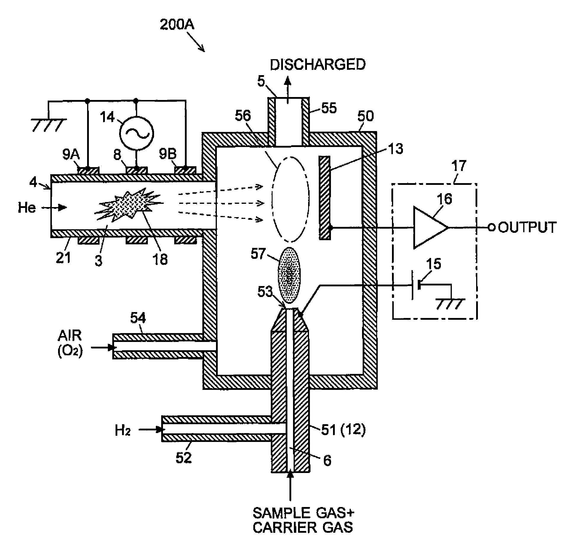
[0123]A discharge ionization current detector according to the first embodiment of the first aspect of the present invention is hereinafter described. FIG. 5 is a schematic configuration diagram of the discharge ionization current detector 200A according to the first embodiment. The same numerals are assigned to the components identical or equivalent to those already described in the previous reference examples.
[0124]The discharge ionization current detector 200A of the present embodiment has a substantially hermetically sealed detection cell 50 having a hydrogen flame formation nozzle 51. A cylindrical pipe 21, combustion air supply pipe 54 and discharge pipe 55 are connected to the detection cell 50. The cylindrical pipe 21 is made of a dielectric material, such as quartz, with a gas passage 3 formed inside. A hydrogen supply pipe 52 is connected to the hydrogen flame formation nozzle 51; the portion of the passage lower than the connection point correspond...
second embodiment
[0130][Second Embodiment]
[0131]A discharge ionization current detector according to the second embodiment of the present invention is hereinafter described. FIG. 6 is a schematic configuration diagram of the discharge ionization current detector 200B according to the second embodiment. The same numerals are assigned to the components identical or equivalent to those already described in the first embodiment and the previous reference examples.
[0132]In the second embodiment, the cylindrical pipe 21 with circumferentially provided plasma generation electrodes 8, 9A and 9B serves as the exhaust pipe and is connected to the ceiling of the detection cell 50 so that it opposes the exit port 53 of the hydrogen flame formation nozzle 51. The ion-current collection electrode 13, which is placed between the hydrogen flame formation nozzle 51 and the cylindrical pipe 21, has a cylindrical shape. This is to increase the area of the electrode.
[0133]In the discharge ionization current detector 20...
third embodiment
[0135][Third Embodiment]
[0136]A discharge ionization current detector according to the third embodiment of the present invention is hereinafter described. FIG. 7 is a schematic configuration diagram of the discharge ionization current detector 200C according to the third embodiment. The same numerals are assigned to the components identical or equivalent to those already described in the first and second embodiments as well as the previous reference examples.
[0137]In the third embodiment, the cylindrical pipe 21 having the plasma generation electrode 8, 9A and 9B is not connected to the detection cell 50 but the inlet end of the hydrogen flame formation nozzle 51. A sample-gas introduction pipe 58 with the sample-gas introduction passage 6 formed inside is connected to a point near the tip of the hydrogen flame formation nozzle 51. The internal passage of the hydrogen flame formation nozzle 51 is widened so that the light emitted from the plasma can easily pass through it.
[0138]In t...
PUM
| Property | Measurement | Unit |
|---|---|---|
| frequency | aaaaa | aaaaa |
| frequency | aaaaa | aaaaa |
| frequency | aaaaa | aaaaa |
Abstract
Description
Claims
Application Information