Control algorithm for autothermal reformer

Inactive Publication Date: 2013-04-30
THE UNITED STATES OF AMERICA AS REPRESENTED BY THE SECRETARY OF THE NAVY
View PDF23 Cites 107 Cited by
  • Summary
  • Abstract
  • Description
  • Claims
  • Application Information

AI Technical Summary

Benefits of technology

[0009]Practice of the inventive control algorithm can render a thermal reformer system more responsive to rapid changes in system load, and more capable of operating at maximum efficiency during steady state conditio

Problems solved by technology

Pure hydrogen is non-toxic, odorless, tasteless, colorless, and easily flammable, and burns in daylight with no visible flame.
Fossil fuels are beset with environmental and economic concerns.
Hydrogen fuel represents a viable alternat

Method used


Image

  • Control algorithm for autothermal reformer
  • Control algorithm for autothermal reformer
  • Control algorithm for autothermal reformer

Examples


Example

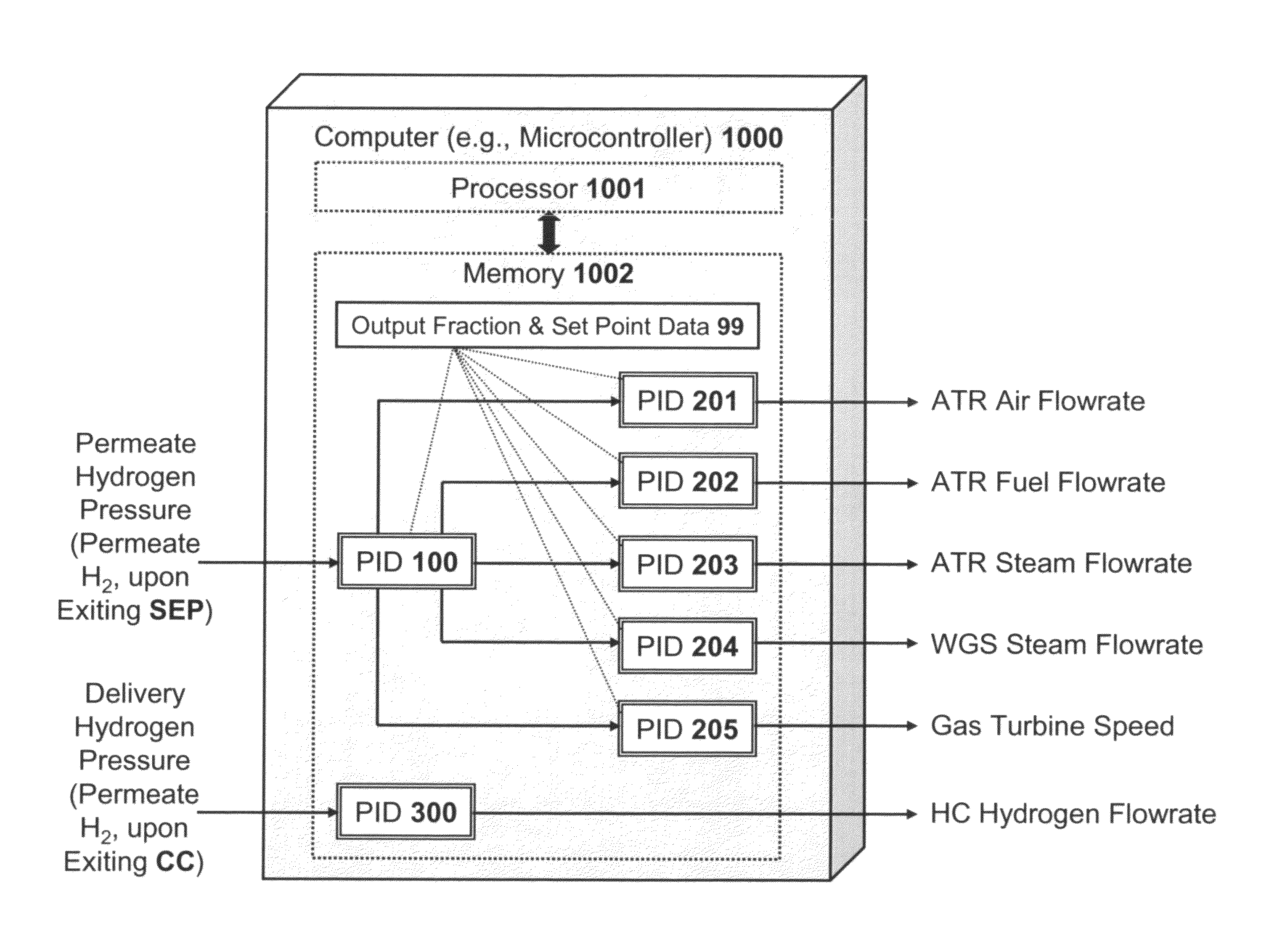
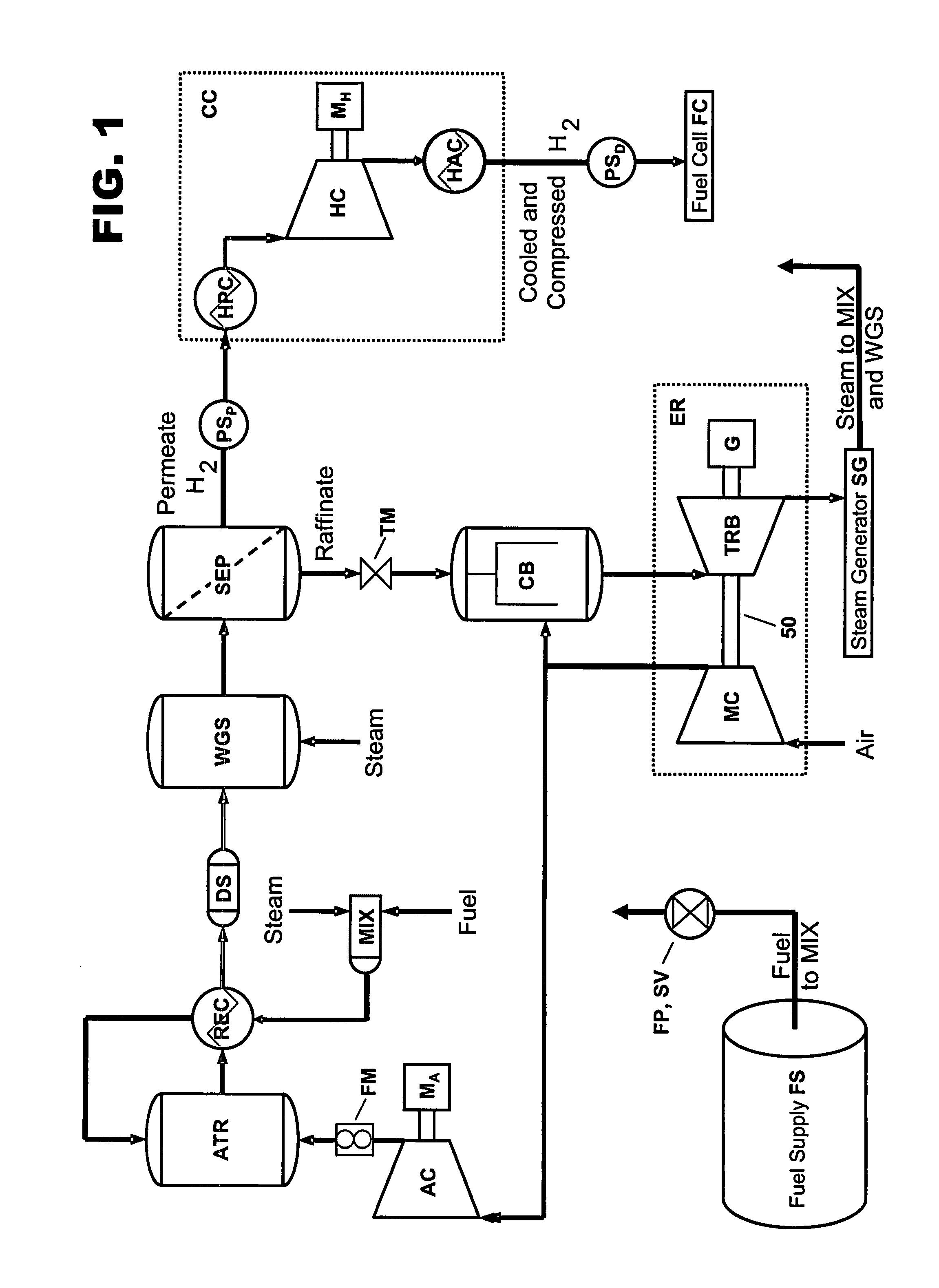
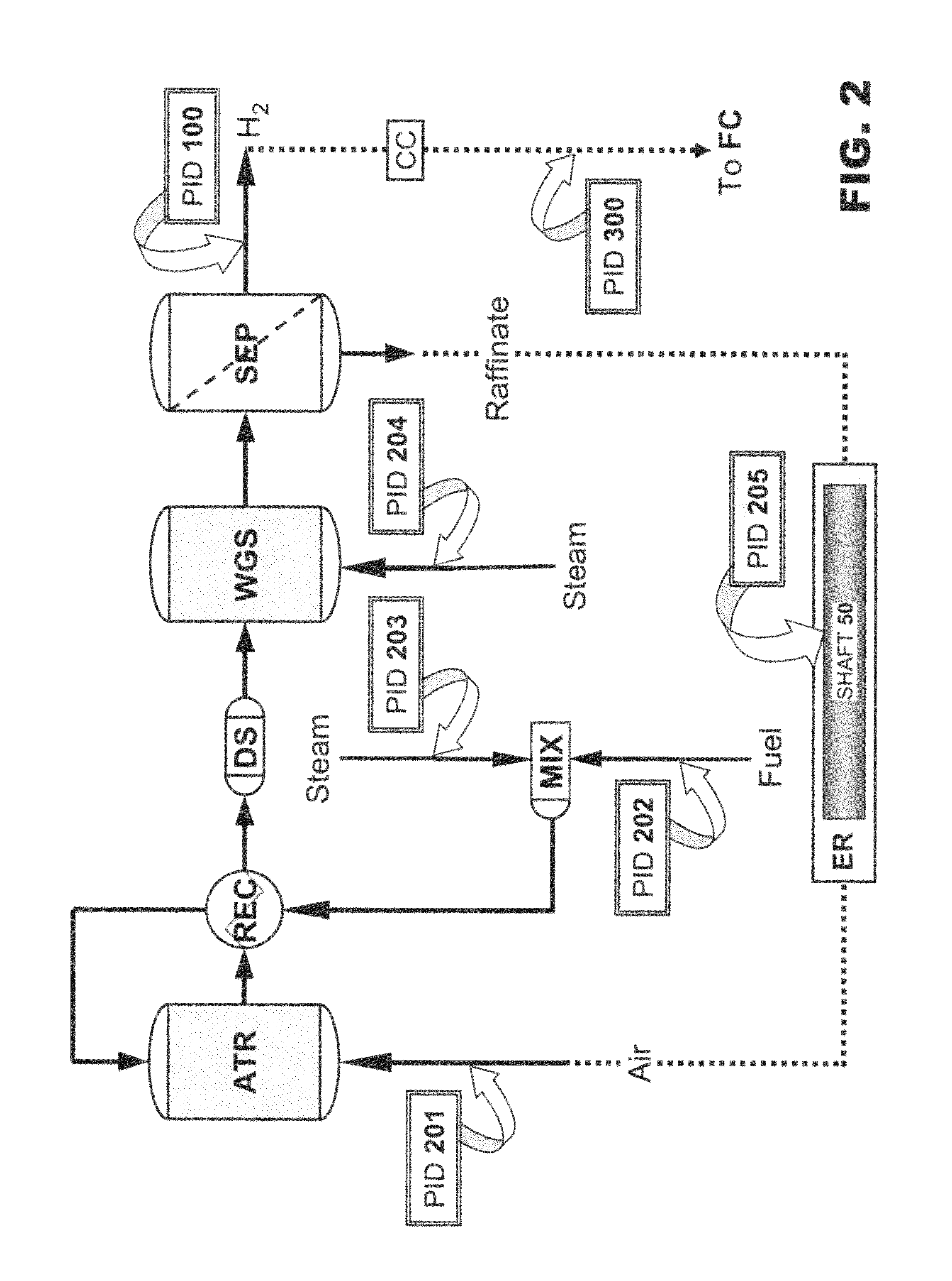
[0027]Reference is now made to FIG. 1 through FIG. 6, which illustrate an autothermal reformer system suitable for practice of inventive algorithmic control. The autothermal reformer system being controlled by the present invention includes three reactors, a separation membrane, a sorbent bed, heat exchangers, pumps, compressors, and a turbine. The inventive algorithm can be practiced in association with an autothermal reformer system lacking a sorbent bed. The United States Navy has demonstrated an autothermal reformer system test prototype similar to that diagrammatically represented in FIG. 1. It is emphasized that the present invention admits of practice involving diesel fuel or any of a variety of other hydrocarbons. It is further emphasized that the present invention admits of practice involving delivery of pure hydrogen to a fuel cell-type device (e.g., fuel cell stack) or to any of a variety of other hydrogen-using devices.

[0028]In this diesel fuel autothermal reformer syste...


PUM


Abstract

According to typical inventive practice, an algorithm controls a reformer in order to produce a pure hydrogen stream for a hydrogen-using device. The inventive algorithmic feedback control maintains the permeate hydrogen stream at a permeate pressure setpoint. Pressure measurements are performed of the permeate hydrogen stream. Control data (e.g., including a “lookup” table) establishes at least three output levels (scaled from zero output to maximum output) of the permeate hydrogen stream and, for each output level, five variable setpoints (air flow rate, hydrocarbon flow rate, and steam flow rate preceding the reformer reaction; steam flow rate preceding the water-gas shift reaction; shaft rotational speed in the energy recovery device). The pressure signals and the control data are processed to determine the optimal output level and the associated variable setpoints. Control signals are sent to adjust the variables to the determined variable setpoints.

Description

CROSS-REFERENCE TO RELATED APPLICATIONS[0001]This application claims the benefit of U.S. provisional patent application No. 60 / 832,009, filing date 13 Jul. 2006, hereby incorporated herein by reference, invention title “Diesel Fuel Autothermal Reformer Control Algorithm,” sole inventor Steven P. Miller.STATEMENT OF GOVERNMENT INTEREST[0002]The invention described herein may be manufactured and used by or for the Government of the United States of America for governmental purposes without payment of any royalties thereon or therefor.BACKGROUND OF THE INVENTION[0003]The present invention relates to hydrogen production, more particularly to methods and apparatuses for producing hydrogen from hydrogenous-carbonaceous substances such as natural gas (e.g., methane, ethane, or propane), organic waste, gasoline, diesel fuel, oil, coal, methanol, and ethanol.[0004]Hydrogen, the most abundant element in the universe, usually occurs in nature as an element included in a compound (e.g., hydroca...

Claims


Application Information

Patent Timeline
IPC IPC(8): G05B15/00C01B3/36
CPCC01B3/382C01B3/48G05B11/01C01B2203/0244C01B2203/0283C01B2203/0405C01B2203/066C01B2203/0883C01B2203/1685C01B2203/169C01B2203/0485
Inventor MILLER, STEVEN P.
Owner THE UNITED STATES OF AMERICA AS REPRESENTED BY THE SECRETARY OF THE NAVY
Why Eureka
Try Eureka