Apparatus and method for non-destructive testing using ultrasonic phased array

a phased array and ultrasonic technology, applied in the direction of analyzing fluids using ultrasonic/ultrasonic/infrasonic waves, instruments, etc., can solve the problems of not being able to test each and every element, analyzing items, and not being able to return optimal acoustic energy to the transmitting transducer, etc., to achieve the effect of increasing or decreasing the volume, increasing or decreasing the pressure in the liquid column

Active Publication Date: 2013-05-14
STRUCTURAL INTEGRITY ASSOC
View PDF17 Cites 12 Cited by
  • Summary
  • Abstract
  • Description
  • Claims
  • Application Information

AI Technical Summary

Benefits of technology

[0033]The present invention is also directed to a wedge that includes a membrane attached to the base and adapted to cover the bottom opening. This membrane seals the liquid column and keeps the liquid from escaping the liquid column. The membrane also can flex and provides a further means of coupling the liquid in the liquid column to the material being analyzed.
[0034]The present invention is further directed to a wedge that includes a liquid inlet port and a screw. The screw can be a pin, plunger or conventional screw. The pin, plunger, or conventional screw is adapted to ingress or egress the wedge housing. This allows increasing or decreasing the volume of said liquid column and, therefore, increasing or decreasing the pressure in said liquid column.
[0039]Still further, the present invention is also directed to a wedge that includes irrigation ports on the housing. The wedge also has a reservoir inside the housing, separate from the liquid column, whereby liquid can flow through the irrigation ports and into and out of the reservoir. The reservoir can be closed or open, thereby allowing liquid to flow out of the wedge between the wedge and the surface of the material being tested. This aids in coupling the wedge to the surface of the material.

Problems solved by technology

Due to the nature of the structural components, it is simply not possible to test each and every element prior to its use.
The value of such testing methods is easily appreciated, because the item being analyzed could be expensive or already part of a larger structure.
Obviously this would be time consuming, expensive, and potentially lead to further problems with removing and replacing certain sections of pipe.
If the defect surface is more than about five degrees off-normal to the direction of propagation, the ultrasonic wave will be reflected but will not return optimal acoustic energy to the transmitting transducer for the defect to be detected.
Unfortunately, problems can occur when the gain is raised to higher levels.
A problem with the higher gain comes in the form of increased wedge and material noise.
Thus, if a pulse-echo configuration is used as opposed to a pitch-catch configuration, the electronic probe can receive noise caused by reflection of the ultrasonic waves from the wedge itself or other variables not present in a pitch-catch configuration.
In any automatic ultrasonic flaw detection system, a major capital cost outlay is the area of the system's electronics for the flaw detection signal processing.
This can be achieved by using large area single element probes for each channel of electronics, but the decrease in resolution of these larger probes often mandates smaller probes with a decreased inspection scan width.
As a result, this increases the number of channels that a system will require for a given scan width.
The damping structure dampens the structural component of the ultrasonic signal to impede propagation of the structural component to the receiver.
A significant problem in each of these prior art patents is present.
The problem, inherent in phased array non-destructive testing, is the inability to scan directly under the surface of the material being scanned with a stationary probe.
Because the phased array transducer, or any other non-destructive testing device, must rest on top of the material being scanned, there is an inability to scan within a certain angle from the surface of the material.
Due to the reflection, the beam has become weakened, thus producing a much weaker signal.
Thus, there exist places where a flaw can exist but cannot be detected without a reflected beam.
However, as seen in the diagram, the prior art detector is unable to sweep the ultrasonic waves at an angle high enough to detect the topmost flaw, closest to the surface.
This is a problem because known techniques of non-destructive, phased array testing can miss flaws in materials because of the difficulty in sweeping the beam at such a high angle.

Method used


Image

  • Apparatus and method for non-destructive testing using ultrasonic phased array
  • Apparatus and method for non-destructive testing using ultrasonic phased array
  • Apparatus and method for non-destructive testing using ultrasonic phased array

Examples


Embodiment Construction

[0057]The present invention will be described herein as it relates to the non-destructive testing of high density polyethylene pipes and joints. Those skilled in the art will quickly realize that the techniques and apparatus described herein can also be used for non-destructive testing on a wide range of materials and objects. Thus, the principle target of inspection, high density polyethylene materials, should not be read as a limitation on the applicability of the present invention.

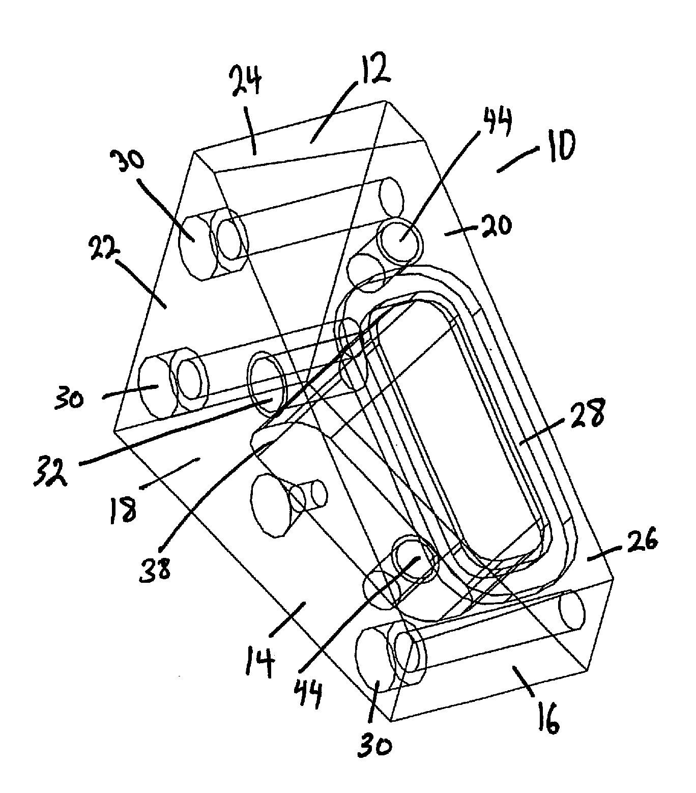
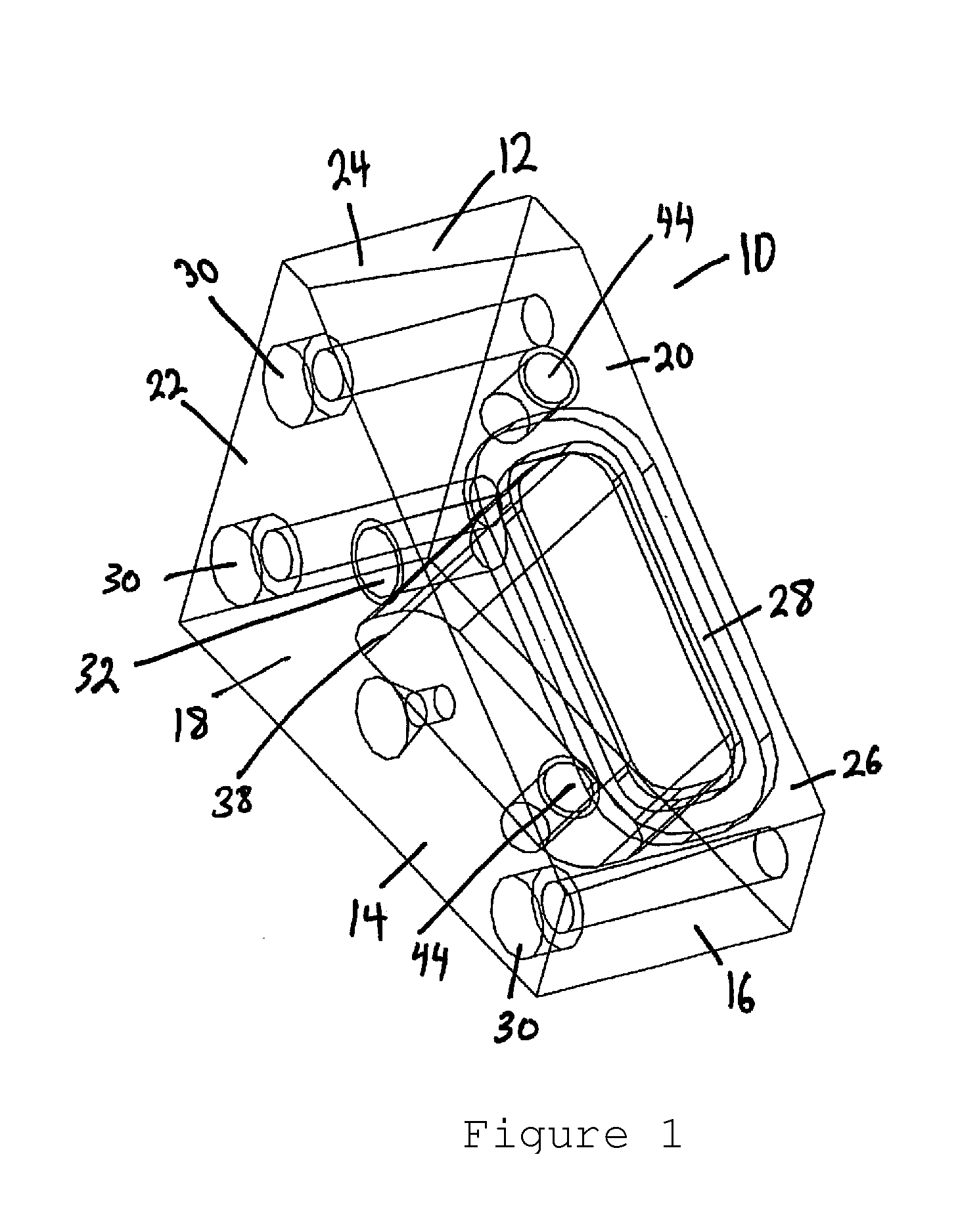
[0058]Referring now to FIG. 1, the wedge 10 is illustrated in its simplest form as a wedge housing 12 that defines a cavity therein. The wedge housing 12 has a base 14, a front side 16, a first side 18, a second side 20, a back side 22, a top surface 24, and a ramp surface 26 that spans between the front side 16 and the top surface 24. The ramp surface 26 defines a top opening 28 generally in a rectangle with rounded corners shape that provides access to the interior of the wedge 10.

[0059]The first side...


PUM

PropertyMeasurementUnit
angleaaaaaaaaaa
angleaaaaaaaaaa
angleaaaaaaaaaa

Abstract

The present invention is related generally to the field of non-destructive materials testing using ultrasonic devices, more particularly, ultrasonic devices in a phased array and includes a wedge for conducting pitch-catch ultrasonic phase array testing of materials wherein the wedge includes a liquid column and is manufactured with specific angles so as to control the angle at which the ultrasonic waves pass into the wedge and then are refracted when passing from the liquid in the liquid column into the material being analyzed, thus providing a wider range of analysis via sweeping the beams from the wedge than was possible with known wedges.

Description

FIELD OF THE INVENTION[0001]The present invention is related generally to the field of non-destructive materials testing using ultrasonic devices, more particularly, ultrasonic devices in a phased array. The present invention relates to a novel wedge design for conducting pitch-catch ultrasonic phase array testing of materials. More specifically, the present invention relates to an apparatus and method to non-destructively and volumetrically examine butt-fusion joints in high-density polyethylene using liquid to achieve refraction of the ultrasonic waves.CROSS-REFERENCE TO RELATED APPLICATION[0002]Not ApplicableBACKGROUND OF INVENTION[0003]As buildings, municipal piping systems, and industrial facilities continue to grow in both size and capacity, the need to verify that the components used to build these systems are working properly and free from defects will continue to rise. Due to the nature of the structural components, it is simply not possible to test each and every element p...

Claims


Application Information

Patent Timeline
Patent Type & Authority Patents(United States)
IPC IPC(8): G01N29/02
CPCG01N29/07G01N29/262G01N29/04G01N2291/0235G01N2291/2675
Inventor FREDERICK, CALEBPORTER, ALLEN
Owner STRUCTURAL INTEGRITY ASSOC
Why Eureka
Try Eureka