Metallic constructions integrity assessment and maintenance planning method

a technology of integrity assessment and maintenance planning, applied in the direction of instruments, hardware monitoring, electric digital data processing, etc., can solve the problems of pipeline failure, large price spike, and large initial investment required for pipelines to be built, and achieve the effect of facilitating structure maintenance and repair scheduling

Active Publication Date: 2013-05-21
GOROSHEVSKIY VALERIAN +2
View PDF3 Cites 50 Cited by
  • Summary
  • Abstract
  • Description
  • Claims
  • Application Information

AI Technical Summary

Benefits of technology

[0029]The method can be applied in general to various extended metallic structures such as pipes, cables, rails, rolled metal products, reservoirs, bridges or vessels, including unpiggable pipelines. The method is especially effective when the remote magnetic tomography (MT) material inspection technique is used, which is based on the inverse magnetostrictive (Villari) effect. This effect is responsible for material magnetic susceptibility changing under applied mechanical stress. Such changing results in distribution of magnetic field gradient along the structure surface area under measurement providing information about the presence / value of the magnetic field anomaly at the given location.
[0032]The disclosed method generates an optimal maintenance schedule using a real-time monitoring without structure operation interruption, including underwater or underground objects. The method also provides ranking the found defects in accordance with their respective risk-factors, thus further facilitating the structure maintenance and repair scheduling.

Problems solved by technology

Like the other modes of transportation, pipelines require very large initial investment to be built, having long exploitation periods when properly maintained.
Like any engineering structure, pipelines do occasionally fail.
While pipeline rates have little impact on the price of a fuel, its disruptions or lack of capacity can constrain supply, potentially causing very large price spikes.
That's why pipelines, such as ones used in the oil and gas industry, require regular inspection and maintenance before potentially costly failures occur.
The major causes of pipeline failures around the world are external interference and corrosion; therefore, assessment methods are needed to determine the severity of such defects when they are detected in pipelines.
Unfortunately, the ILI using intelligent pigging is unavailable for a wide range objects that require full disruptive inspection and significant spending on repair preparation.
While the ILI method is suitable for the initial flaw detection, it is less efficient for the relative degree (ranking) of the risk-factor evaluation, as well as for defective pipeline serviceability calculation.
Pipe-line pigging is a very expensive and labor-consuming method.
The major limitation of this method is the fact that a large part of pipe-lines are not prepared to be used, e.g. due to lack of input / output chambers for pig-flow device launching and pipe-line cleaning access, partially blocked pipe cross-section due to the welding artifacts, geometrical abnormalities and large slopes (small radius turns) of the pipe-line layout.
This causes future technical problems of the pipeline demagnetization that required for actual pipe repair after the pigging.
Moreover, the evaluation of the absolute values of mechanical flaws by pigging is particular difficult due to the multiple additional factors that have to be taken into account, e.g. bearing capacity of the soil, local cyclical loads (temperature, etc.).
It translates into risk factors such as the toxicity, the proximity to the valuable property, etc.
The disadvantage of this method is a limited area of application where the heat-transferring objects, such as heating infrastructure, are present.
Moreover, this method is effective only at the stage when the fracture and leakage have already been developed, causing the excessive heat radiation around the defective areas.

Method used


Image

  • Metallic constructions integrity assessment and maintenance planning method
  • Metallic constructions integrity assessment and maintenance planning method
  • Metallic constructions integrity assessment and maintenance planning method

Examples


Embodiment Construction

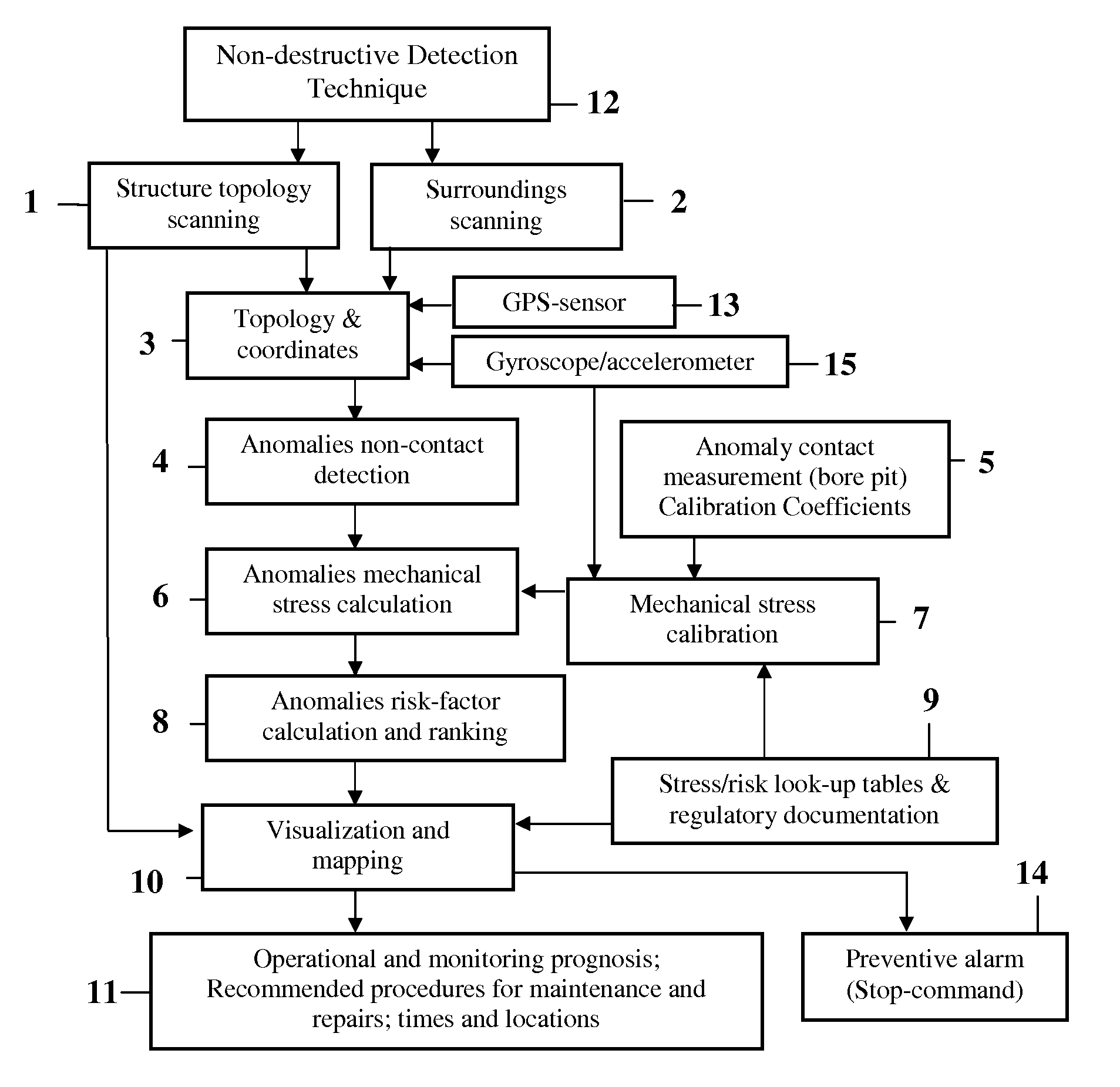
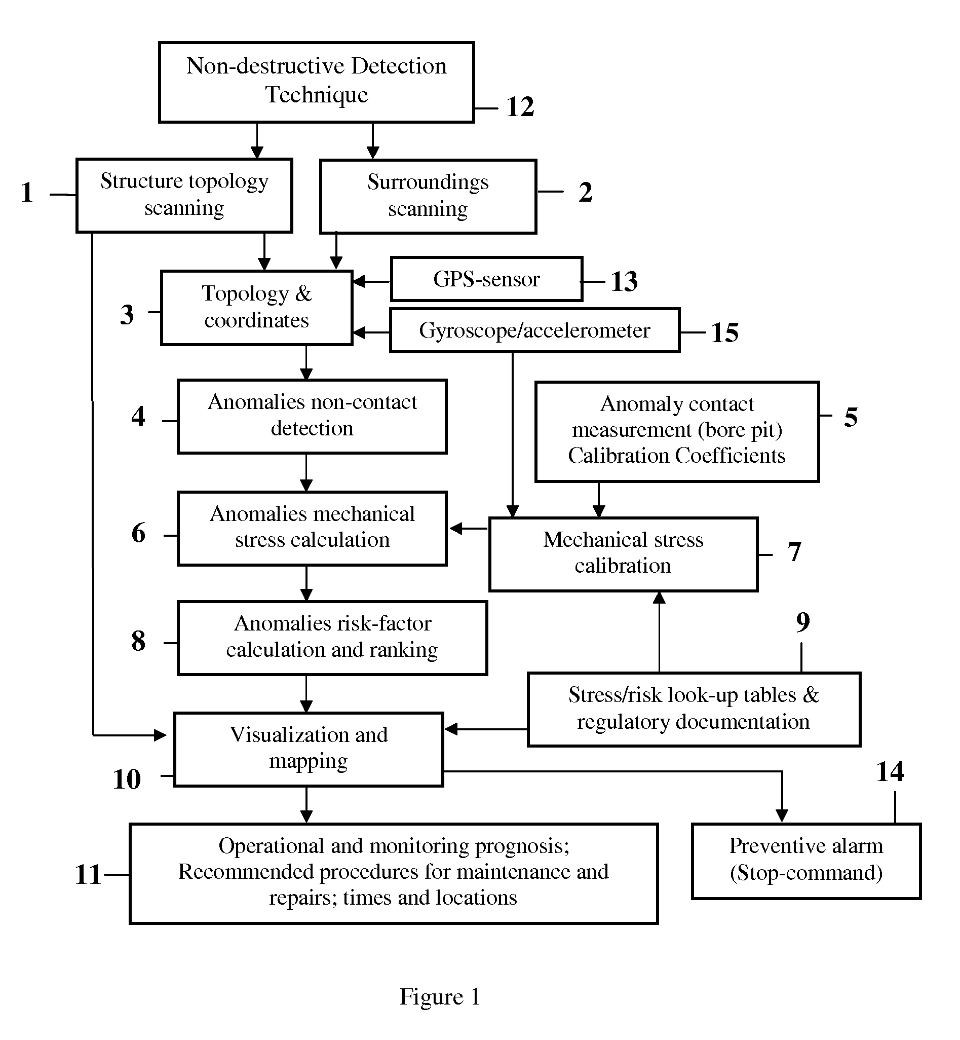
[0037]The present invention describes the magnetographic technique, the magnetic tomography (MT), and the maintenance timeline planning method (priority steps), optimized for extended metallic constructions. The block-diagram of the method is given in FIG. 1.

[0038]The method includes (with reference to FIG. 1): Precise scanning (1) using the non-destructive magneto-graphic (such as MT) anomalies detection technique (12) for (axial) localization of the extended metallic structure (e.g. subterranean or submarine pipeline), as well as surrounding scanning (2) for identification of other possible objects in the vicinity of the structure, including hidden objects (pipes, cables) detection (4) and identification of the defective segments or areas of the said structure, in general, by using thermo-visual imaging, magneto-graphic methods or by other remote (non-contact, non-destructive) methods; accurate location of different types of anomalies by using thermal and magnetic non-contact scan...


PUM

PropertyMeasurementUnit
metallicaaaaaaaaaa
magnetic fieldaaaaaaaaaa
stressaaaaaaaaaa

Abstract

A method for metallic structure maintenance is disclosed. The method includes a magneto-graphic / Magnetic Tomography technique to identify stress-related defects. The method is specifically optimized for extended, non-accessible underground and underwater metallic structures in providing quality control, emergency alarms as well as timeline planning for structural repairs and maintenance work. Examples of the method implementation include pipes for oil and gas industry, detection of flaws in rolled products in metallurgical industry, welding quality of heavy duty equipment such as ships reservoirs, etc. It is especially important for loaded constructions, such as pressured pipes, infrastructure maintenance, nuclear power plant monitoring, bridges, corrosion prevention and environment protection.

Description

FIELD OF INVENTION[0001]The present invention relates broadly to a method and technique for continuous (extended) metallic constructions inspection and monitoring for possible defects; in particular, to methods and devices for magneto-graphic quality control and method of planning a sequence (priority order) of required repairs and maintenance work. The method also provides a real-time monitoring of the structure operational condition.BACKGROUND OF THE INVENTION[0002]This invention can be used in various fields where constructions are tested for continuity defects in not-so-easily accessible areas; examples of technology implementation may include pipes for oil and gas industry, detection of flaws in rolled products in metallurgical industry, welding quality of heavy duty equipment such as ships and reservoirs, etc. It is especially important for loaded constructions, such as pressured pipes, infrastructure maintenance, nuclear power plant monitoring, bridges, corrosion prevention a...

Claims


Application Information

Patent Timeline
Patent Type & Authority Patents(United States)
IPC IPC(8): G01L1/12
CPCG01L1/125B23K31/003
Inventor GOROSHEVSKIY, VALERIANKAMAEVA, SVETLANAKOLESNIKOV, IGORIVLEV, LEONID
Owner GOROSHEVSKIY VALERIAN
Why Eureka
Try Eureka