Techniques for debris reduction when performing edge deletion on coated articles having temporary protective coatings applied thereto

a coating and coating technology, applied in the direction of grinding/polishing apparatus, grinding machine components, grinding machines, etc., can solve the problems of high risk of damage, easy high risk of damage to the coating side of the coating sheet, so as to reduce the scattering of debris, reduce yield, and easy removal

Inactive Publication Date: 2013-05-28
GUARDIAN EURO S A R L
View PDF13 Cites 17 Cited by
  • Summary
  • Abstract
  • Description
  • Claims
  • Application Information

AI Technical Summary

Benefits of technology

[0006]Glass coating companies often require coating edge deletion for many of their products, for example, to help ensure proper adhesion of materials such as sealants to their glass surfaces. In this regard, edge deletion tables are known. See, for example, U.S. Pat. Nos. 4,716,686; 5,713,986; 5,934,982; 6,971,948; 6,988,938; 7,125,462; and 7,140,953, each of which is hereby incorporated herein in its entirety. A series of casters provided to the table allow for smooth movement of glass across the surface of the table. Grinding wheels of various widths may be used in connection with shields to help reduce the scattering of debris and for safety purposes. Passing the glass substantially consistently under the deletion head efficiently “deletes” the coating from the glass so that it can be used, for example, with sealants in intermediate or finished products. Wider or narrower grinding wheels may be used to delete more or less coating from the glass surface.
[0007]It will be appreciated that it would be advantageous to perform edge deletion when a temporary protective coating is on a coated article, e.g., without having to remove the temporary protective coating from the area where edge deletion is to be performed. Unfortunately, however, this is not possible using current apparatuses. Indeed, current apparatuses are designed only to edge delete the coating disposed on the substrate. Thus, the temporary protective coating needs to be at least partially removed prior to edge deletion. However, removing too much of the temporary protective coating exposes the underlying coated substrate, whereas removing too little will hamper, and often completely prevent, proper edge deletion. In either case, the manual or even machine removal of the temporary protective coating introduces additional process steps and / or risks damage to the articles and / or machinery involved, thus injecting delays into the process, reducing yield, and increasing costs.
[0009]Thus, it will be appreciated that there is a need in the art for techniques for edge deleting coatings provided to coated articles when temporary protective coatings are applied thereto, e.g., at a common area of interest. It also will be appreciated that, as a part of such techniques, it would be advantageous to control the debris produced when edge deletion is performed on a coated article having a temporary protective coatings applied thereto.

Problems solved by technology

Coated glass sheets often are easily damaged.
Indeed, glass sheets often are highly susceptible to damage during cutting, loading / unloading from glass racks or pallets, shipment, edge seaming, post-washing handling, etc.
The coated side of the coated sheets are the most vulnerable to damage (e.g., scratching and the like) in this regard.
For example, coated sheets are often scratched due to one or more of rubbing up against other sheets or the like during shipment, pliers used by glass handlers, abrasion caused by gloves worn by glass handlers, brushes used during the washing, and other types of rubbing / abrasion.
Additionally, corrosion is also a significant cause of damage and often is caused by high humidity conditions, acid rain, and / or other materials which tend to collect on the coated articles during transport, storage and / or handling.
While the aforesaid types of damage often occur prior to heat treatment (e.g., tempering), the tempering of the coated sheets typically magnifies such damage.
For example, a minor bit of corrosion which was caused pre-tempering can lead to a significant blemish upon heat treatment which causes the coated sheet to be scrapped.
Thus, the damage to a coated article often tends to be worse following heat treatment.
Accordingly, it can be seen that yields appreciably suffer due to pre-HT damage that tends to occur to coated glass sheets.
Unfortunately, however, this is not possible using current apparatuses.
However, removing too much of the temporary protective coating exposes the underlying coated substrate, whereas removing too little will hamper, and often completely prevent, proper edge deletion.
In either case, the manual or even machine removal of the temporary protective coating introduces additional process steps and / or risks damage to the articles and / or machinery involved, thus injecting delays into the process, reducing yield, and increasing costs.
Simply attempting to perform edge deletion with the temporary protective coating on the coated article does not work, as the edge deletion table is not designed to work in this way.
Indeed, sometimes the temporary protective coating is removed and only part of the coating disposed on the substrate is removed, whereas other times the coating may be marred or otherwise damaged but not sufficiently deleted.
The temporary protective coating may wrinkle or otherwise become deformed or damaged adjacent the portion where edge deletion is supposed to occur.
A significant amount of debris also is typically produced when edge deletion with the temporary protective coating on the coated article is attempted, and this debris often will contaminate the room, remain on or otherwise negatively impact the substrate, create problems for the edge deletion unit (such as, for example, clogging, etc.), and / or lead to other drawbacks.

Method used


Image

  • Techniques for debris reduction when performing edge deletion on coated articles having temporary protective coatings applied thereto
  • Techniques for debris reduction when performing edge deletion on coated articles having temporary protective coatings applied thereto
  • Techniques for debris reduction when performing edge deletion on coated articles having temporary protective coatings applied thereto

Examples


Embodiment Construction

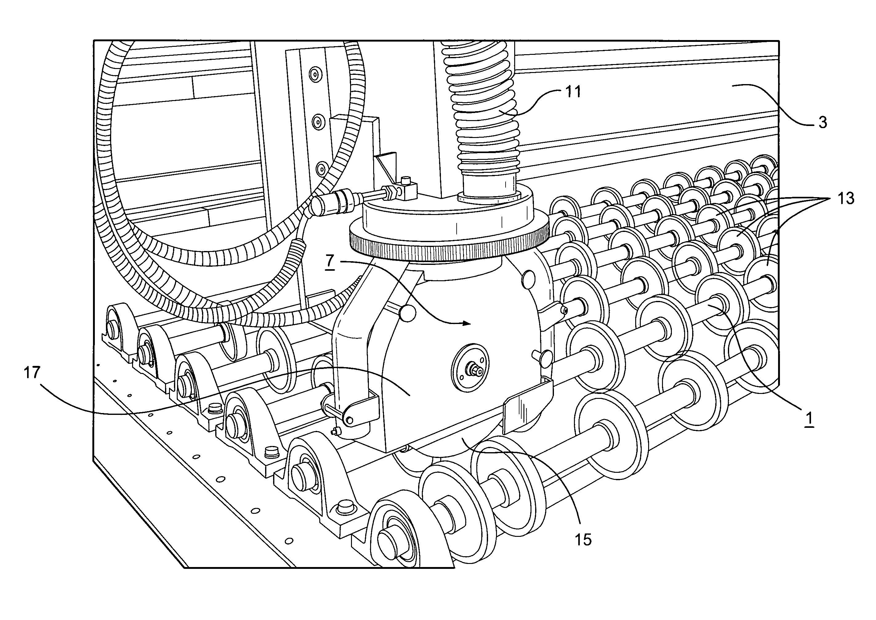
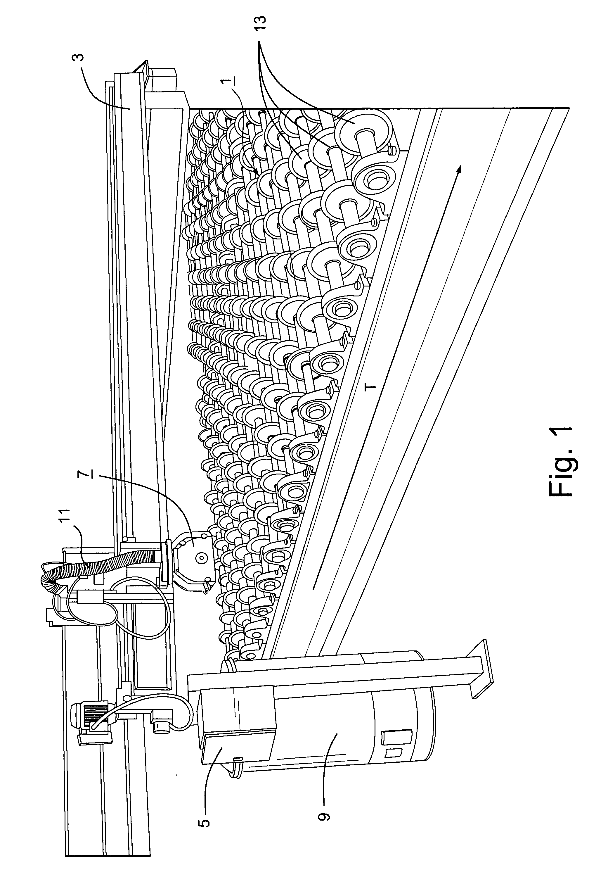
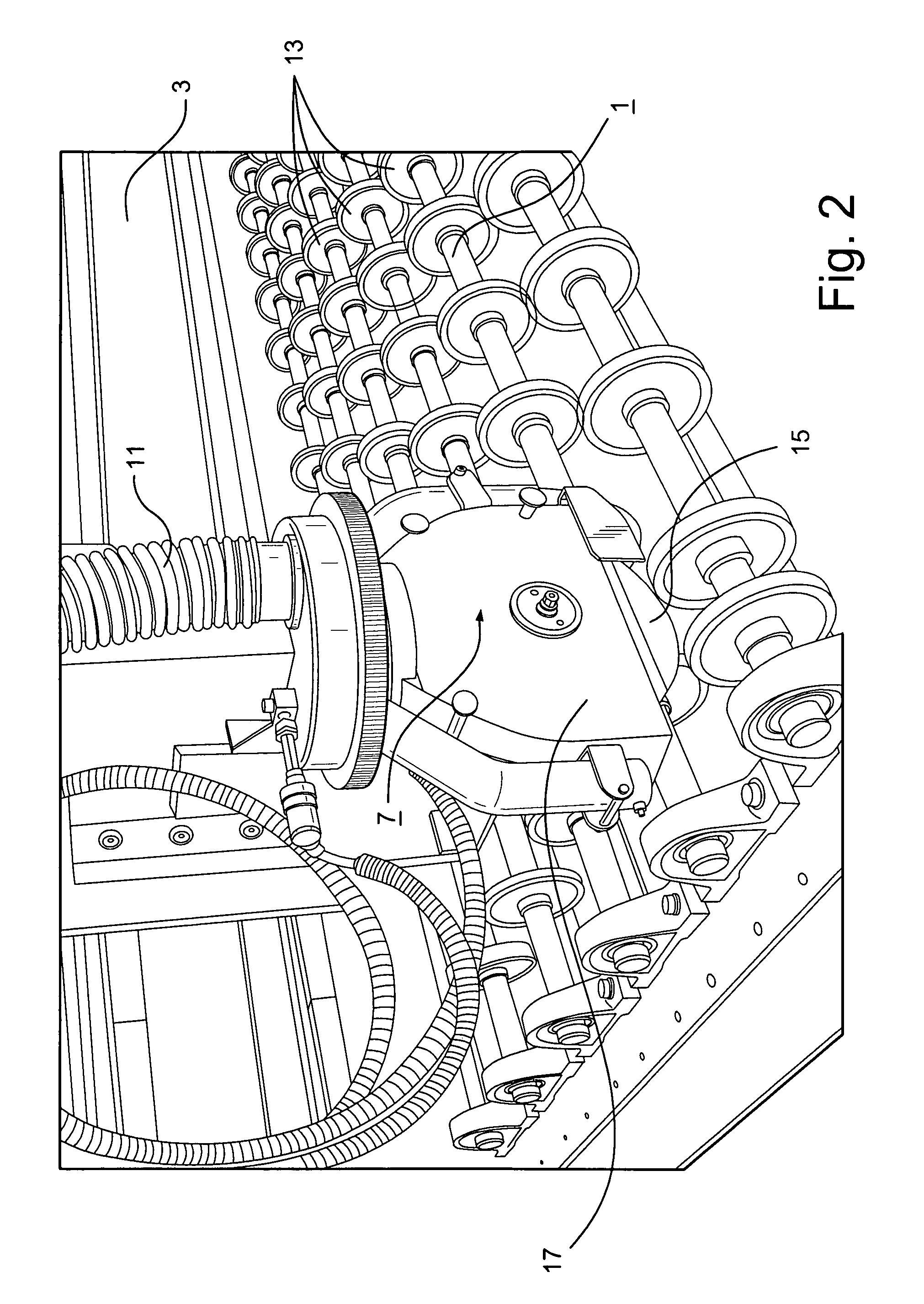
[0020]Certain example embodiments of this invention relate to techniques for debris reduction when performing edge deletion on coated articles having temporary protective coatings applied thereto. In certain example embodiments, a stationary (at least in operation), enlarged, and higher powered aspirator connected to flexible tubing, which itself has an enlarged diameter, that has a nozzle located proximate to a grinding wheel on an edge deletion unit is provided in connection with an edge deletion table. Advantageously, the edge deletion table and aspirator of certain example embodiments are capable of performing edge deletion and removal of a temporary protective coating substantially simultaneously, e.g., at a common area of interest, during which process the debris produced when edge deletion is performed is controlled and removed from the substrate of interest.

[0021]Referring now more particularly to the accompanying drawings in which like reference numerals indicate like parts...


PUM

PropertyMeasurementUnit
diameteraaaaaaaaaa
diameteraaaaaaaaaa
diameteraaaaaaaaaa

Abstract

Certain example embodiments of this invention relate to techniques for edge deleting coatings supported by coated articles while a temporary protective coating is applied thereto. More particularly, a stationary, enlarged, and higher powered aspirator is connected to flexible tubing, which itself has an enlarged diameter, that has a nozzle located proximate to a grinding wheel on an edge deletion unit is provided in connection with an edge deletion table. Advantageously, the edge deletion table and aspirator of certain example embodiments are capable of performing edge deletion and removal of a temporary protective coating substantially simultaneously (e.g., from a common area of interest), during which process the debris produced when edge deletion is performed is controlled and removed from the substrate of interest.

Description

FIELD OF THE INVENTION[0001]Certain example embodiments of this invention relate to edge deletion for coated articles. More particularly, certain example embodiments of this invention relate to techniques for edge deleting coatings provided to coated articles when temporary protective coatings are applied thereto, e.g., at common areas of interest. Additionally, certain example embodiments advantageously make it possible to control the debris produced when edge deletion is performed on a coated article having a temporary protective coatings applied thereto.BACKGROUND AND SUMMARY OF EXAMPLE EMBODIMENTS OF THE INVENTION[0002]Coated glass sheets often are easily damaged. For example, coated glass sheets sometimes are less durable while in the annealed state (e.g., prior to tempering). Indeed, glass sheets often are highly susceptible to damage during cutting, loading / unloading from glass racks or pallets, shipment, edge seaming, post-washing handling, etc. The coated side of the coated...

Claims


Application Information

Patent Timeline
Patent Type & Authority Patents(United States)
IPC IPC(8): B24B49/00B24B1/00
CPCB24B9/102B24B55/06
Inventor SONDAG, PETER
Owner GUARDIAN EURO S A R L
Why Eureka
Try Eureka