Thermally assisted magnetic head assembly and magnetic disk device

a magnetic head and magnetic disk technology, applied in the field of magnetic head assembly and magnetic disk device, can solve the problems of reducing light intensity, absorption loss and scattering loss, difficult recording by a conventional magnetic head, etc., and achieves satisfactory optical coupling, high efficiency, and suppress position deviation

Inactive Publication Date: 2013-07-02
HITACHI LTD
View PDF14 Cites 12 Cited by
  • Summary
  • Abstract
  • Description
  • Claims
  • Application Information

AI Technical Summary

Benefits of technology

[0027]According to the present invention, it is possible to suppress position deviation between the slider and the submount, and thus realize satisfactory optical coupling. In addition, because at least parts of the adhesives are applied to the position opposed to the semiconductor laser, heat of the semiconductor laser can be released to the slider side with high efficiency. Accordingly, non-uniform deformation of the slider during an operation of the semiconductor laser can be reduced. As a result, an excellent floating property can be satisfied, and an extension of the lifetime of the semiconductor laser can be realized. In this way, a thermally assisted magnetic recording head assembly which can deal with high density recording can be realized.

Problems solved by technology

The adoption of this method makes it possible to facilitate recording into a recording medium having such a high retention force that recording by a conventional magnetic head is difficult due to an insufficient recording magnetic field intensity.
Main causes of the decrease in light intensity include: absorption loss and scattering loss when the light passes through the optical components; coupling loss resulting from deviation from an ideal position which occurs at the time of mounting or adhesion of the optical components and at the time of soldering; and the like.
However, in the case of the further advance in downsizing and the smaller floating amount, it is predicted that warpage of the slider itself will become a big problem.
However, it is known that, because the semiconductor laser itself becomes a heat source, if uniform heat radiation to the slider is not possible, deformation of the slider due to the heat is accelerated, and the lifetime of the semiconductor laser is degraded.

Method used


Image

  • Thermally assisted magnetic head assembly and magnetic disk device
  • Thermally assisted magnetic head assembly and magnetic disk device
  • Thermally assisted magnetic head assembly and magnetic disk device

Examples


embodiment 1

(1) Embodiment 1

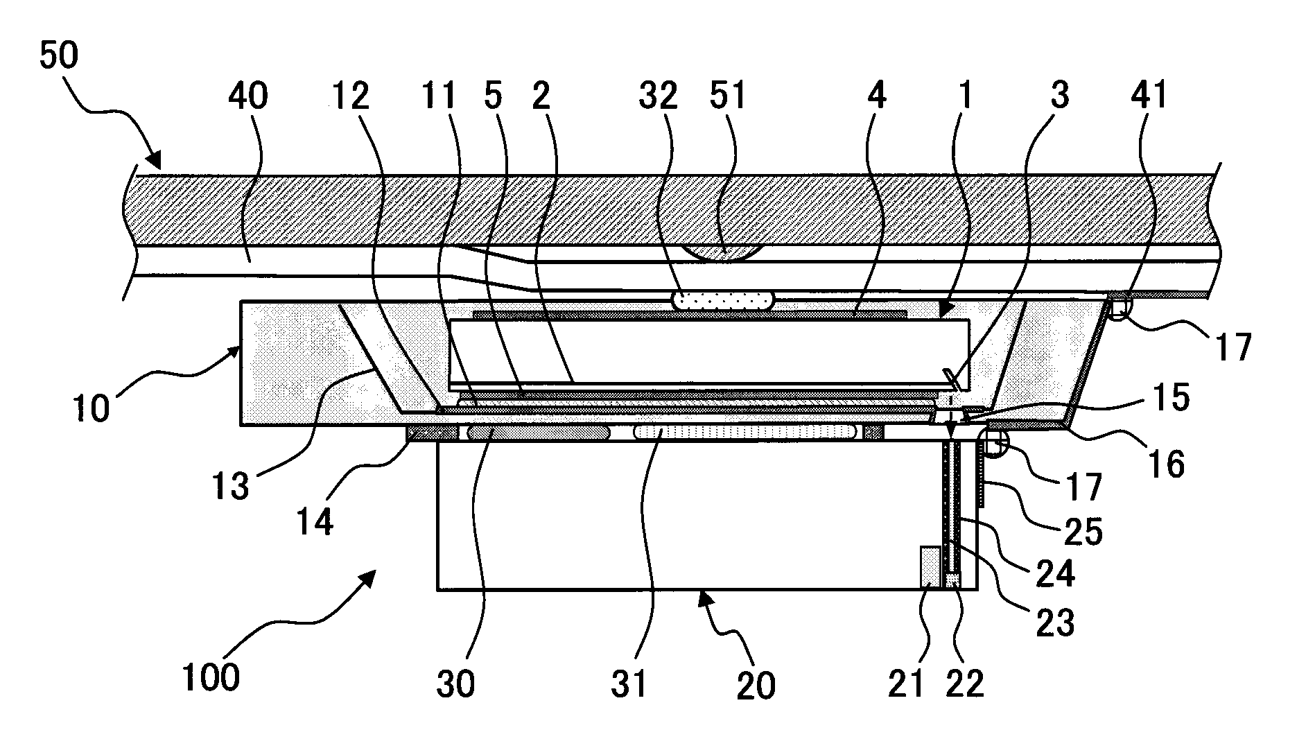
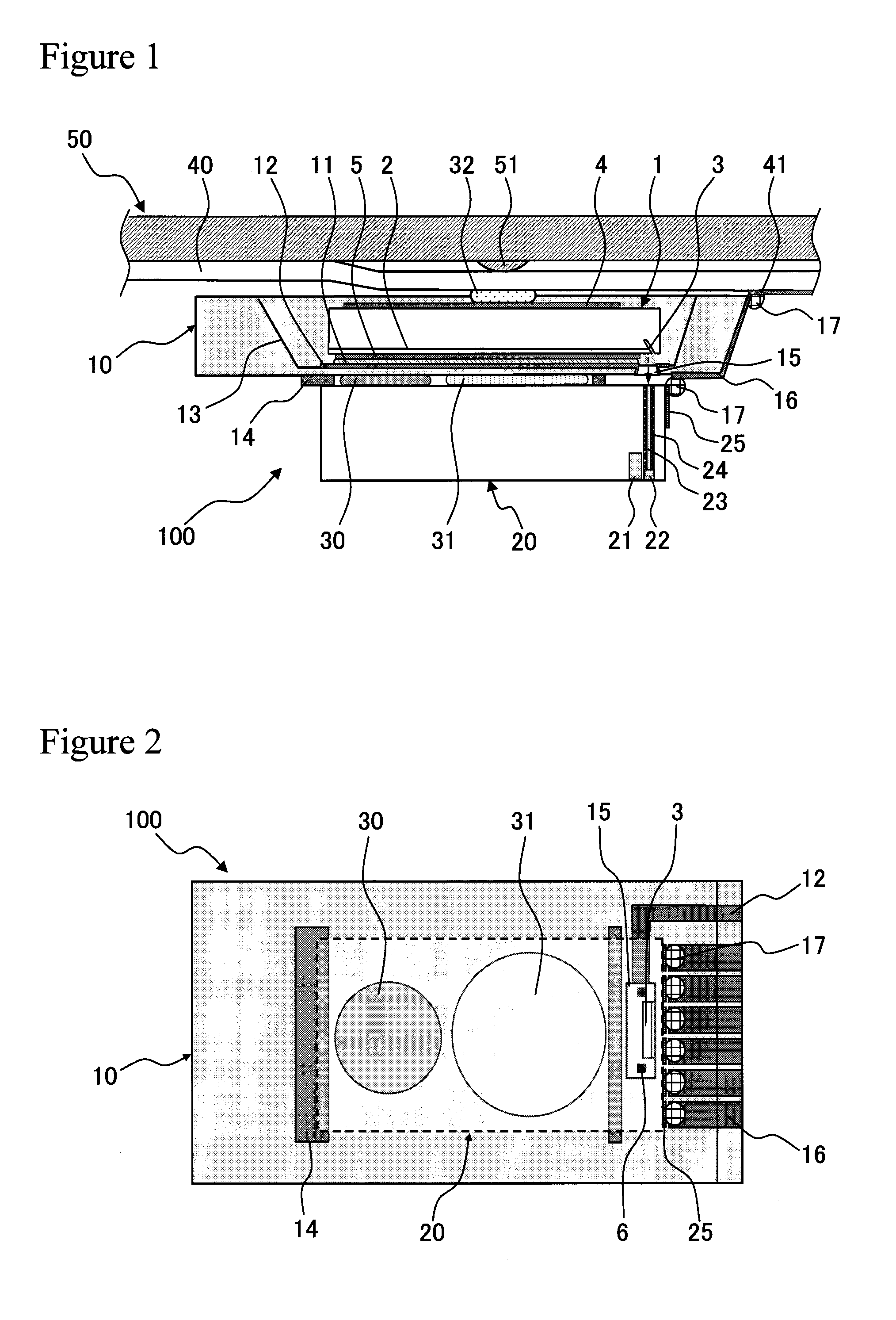
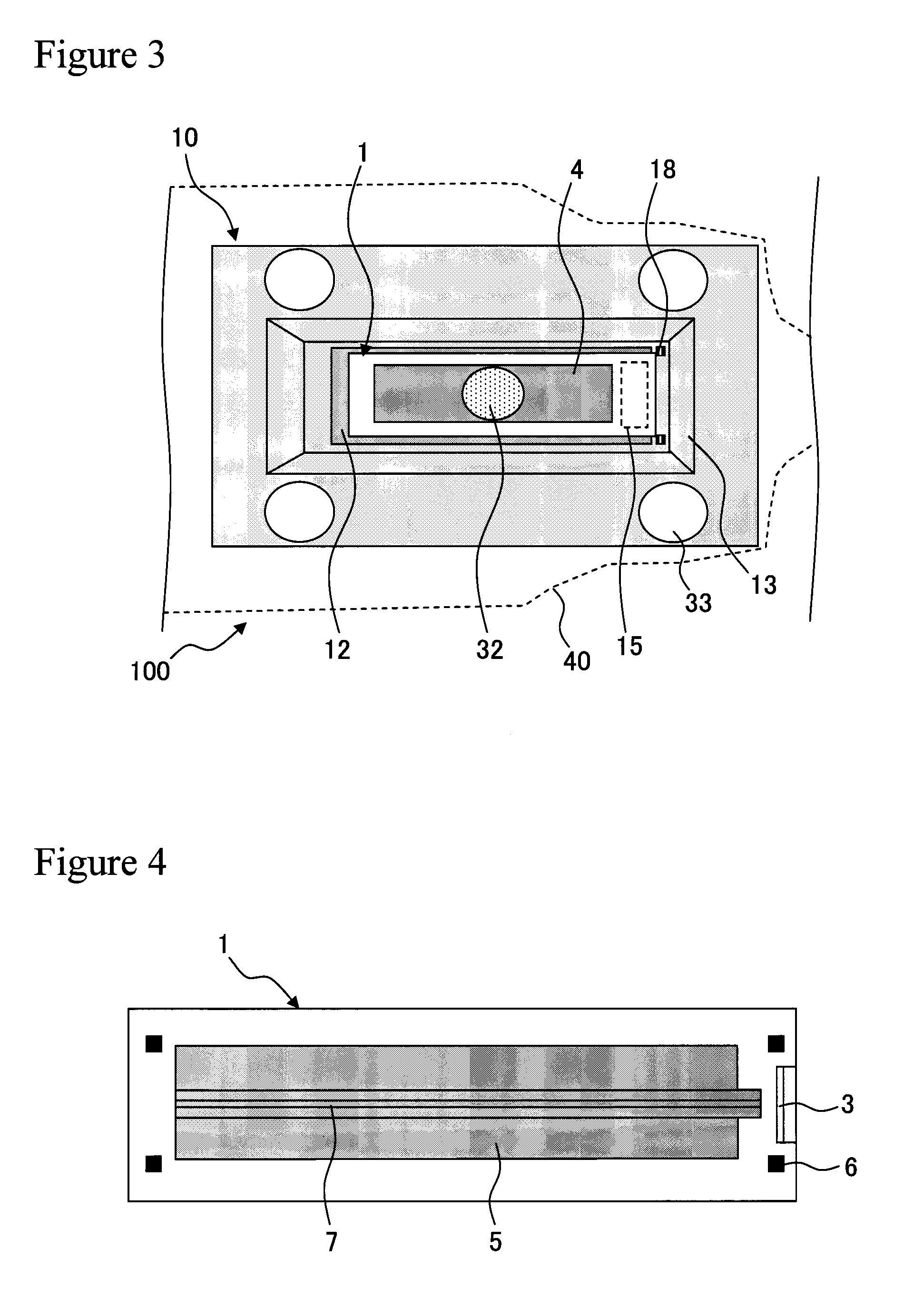
[0047]FIG. 1 illustrates a cross sectional structure example of a thermally assisted magnetic recording head assembly 100 according to Embodiment 1. As illustrated in FIG. 1, the thermally assisted magnetic recording head assembly 100 includes a submount 10, a slider 20, and two types of adhesives 30 and 31 which fix these members to each other. A through hole 15 is formed in the submount 10 so as to face an optical waveguide formed on the slider 20 side. A semiconductor laser 1 is mounted on the submount 10, and a reflection mirror 3 is formed in the semiconductor laser 1 so as to guide laser light to the through hole 15. Specifically, the reflection mirror 3 is formed near an end surface of the semiconductor laser 1. The optical waveguide (a core 23 and a clad 24), a near field generation element 22, and a magnetic recording / detection element 21 are mounted on the slider 20. At least part of the two types of adhesives 30 and 31 which fix the submount 10 and the sli...

embodiment 2

(2) Embodiment 2

[0068]FIG. 6 illustrates a planar structure example of the thermally assisted magnetic recording head assembly 100 according to Embodiment 2, which is observed from the slider 20 side. In the case of the present embodiment, the first adhesive 30 is applied a plurality of times (in the case of this figure, twice). This largely changes an apparent length of the first adhesive 30 in the short-side (width) direction of the slider 20. Normally, when an adhesive is applied by using a dispenser or the like, the adhesive is applied in the direction perpendicular to the submount 10 from the point of view of control. Therefore, the shape of the adhesive after application and mounting becomes a shape close to a circle. In the deformation of the slider 20, particularly, a change in the long-side direction has a more harmful influence on the floating property than a change in the short-side direction. In view of this, the first adhesive 30 is applied a plurality of times, to ther...

embodiment 3

(3) Embodiment 3

[0069]FIG. 7 illustrates a planar structure example of the thermally assisted magnetic recording head assembly 100 according to Embodiment 3, which is observed from the slider 20 side. The present embodiment adopts a structure in which the second adhesive 31 is surrounded by the stud 14. As a matter of course, the stud 14 is formed first. FIG. 8 illustrates a cross sectional structure example of the thermally assisted magnetic recording head assembly 100 according to the present embodiment. An adhesive not containing filler is used as the second adhesive 31, which enables a smaller thickness and a lower Young's modulus. In return, the viscosity becomes excessively low in some cases. In such a case, when the stud 14 is placed around the second adhesive 31, even if the second adhesive 31 spreads out at the time of application, the adhesive is prevented from flowing out of the slider 20, and the area thereof can be controlled to some degree.


PUM

PropertyMeasurementUnit
sizeaaaaaaaaaa
distanceaaaaaaaaaa
thicknessaaaaaaaaaa

Abstract

A slider including a magnetic head part, an optical waveguide, and a near field element is fixed by first and second adhesives to a submount on which a semiconductor laser and a mirror are mounted, the mirror being placed at one end of the semiconductor laser in a resonance direction thereof and reflecting a laser in a direction intersecting with the resonance direction. At this time, at least parts of the first and second adhesives are applied to a position opposed to the semiconductor laser with an intermediation of the submount. The first adhesive having a higher Young's modulus than that of the second adhesive is applied onto an inflow end side of the slider including a solder connection portion, the second adhesive being applied onto an outflow end side of the slider.

Description

TECHNICAL FIELD[0001]The present invention relates to a technology of mounting a thermally assisted magnetic recording head assembly which applies a magnetic field to a magnetic recording medium heated by near field light to thereby record information. Specifically, the present invention relates to an adhesion structure between a slider on which an element for thermally assisted magnetic recording is mounted and a submount on which a semiconductor laser is mounted. In addition, the present invention relates to a magnetic disk device on which the thermally assisted magnetic head assembly including the adhesion structure is mounted.BACKGROUND ART[0002]In recent years, an optical-magnetic hybrid recording technology in which optical recording and magnetic recording are combined with each other has been proposed as one of technologies for improving a recording density of a magnetic disk device. This technology adopts a method of heating, at the time of recording, a medium at the same ti...

Claims


Application Information

Patent Timeline
Patent Type & Authority Patents(United States)
IPC IPC(8): G11B11/00
CPCG11B5/314G11B5/4833G11B5/4866G11B2005/0021
Inventor ARAI, SATOSHINANIWA, IRIZOSHIMIZU, JUNICHIROMATSUMOTO, TAKUYASASAKI, SHIGEYUKI
Owner HITACHI LTD
Why Eureka
Try Eureka