Photobioreactor cell culture systems, methods for preconditioning photosynthetic organisms, and cultures of photosynthetic organisms produced thereby

a photobioreactor and cell culture technology, applied in the field of photobioreactor cell culture systems, methods for preconditioning photosynthetic organisms, and cultures of photosynthetic organisms produced thereby, can solve the problems of inability to achieve the rate-limiting step in the aqueous phase, and inability to achieve commercial success to date, so as to achieve the effect of reducing the growth ra

Inactive Publication Date: 2013-08-13
THE TRON GRP +1
View PDF268 Cites 10 Cited by
  • Summary
  • Abstract
  • Description
  • Claims
  • Application Information

AI Technical Summary

Problems solved by technology

In addition, algae are capable of growing in saline waters that are unsuitable for agriculture.
Although photosynthesis is fundamental to the conversion of solar radiation into stored biomass, efficiencies can be limited by the limited wavelength range of light energy capable of driving photosynthesis (400-700 nm, which is only about half of the total solar energy).
The dissolution of NO in the aqueous phase is believed to be the rate-limiting step in this NOX removal process.
Each program took a different approach, but because of various problems addressed by certain embodiments of the present invention, none has been commercially successful to date.
A major obstacle for feasible algal bio-regeneration and pollution abatement has been an efficient, yet cost-effective, growth system.
The ponds require low capital input; however, algae grown in open and uncontrolled environments result in low algal productivity.
The open pond technology made growing and harvesting the algae prohibitively expensive, since massive amounts of dilute algal waters required very large agitators, pumps and centrifuges.
Furthermore, with low algal productivity and large flatland requirements, this approach could, in the best-case scenario, be applicable to only 1% of U.S. power plants.
On the other hand, the MITI approach, with stricter land constraints, focused on very expensive closed algal photobioreactors utilizing fiber optics for light transmission.
In these controlled environments, much higher algal productivity was achieved, but the algal growth rates were not high enough to offset the capital costs of the expensive systems utilized.
These bioreactors, when oriented horizontally, typically require additional energy to provide mixing (e.g., pumps), thus adding significant capital and operational expense.
Photobioreactors that do not utilize solar energy but instead rely solely on artificial light sources can require enormous energy input.
Since no precisely defined flow lines are reproducibly formed, it can be difficult to control the mixing properties of the system which can lead to low mass transfer coefficients, poor photomodulation, and low productivity.
However, control over the flow patterns within an air lift reactor to achieve a desired level of mixing and photomodulation can still be difficult or impractical.
In addition, because of geometric design constraints, during large-scale, outdoor algal production, both types of cylindrical-photobioreactors can suffer from low productivity, due to factors related to light reflection and auto-shading effects (in which one column is shading the other).
Another problem in utilizing conventional algal culture technology and conventional commercially available algal cultures for pollution mitigation on-site in photobioreactors is that commercially available cultures of species suitable for pollutant abatement are typically poorly suited to grow under light and other conditions that the algae will experience in operation.
This can lead to a failure of the culture and photobioreactor system and / or to infiltration of the photobioreactor by parasitic organisms better suited to growth under the prevailing conditions, but that are unable or poorly suited to abatement of pollutants, such as NOx and SOx.

Method used


Image

  • Photobioreactor cell culture systems, methods for preconditioning photosynthetic organisms, and cultures of photosynthetic organisms produced thereby
  • Photobioreactor cell culture systems, methods for preconditioning photosynthetic organisms, and cultures of photosynthetic organisms produced thereby
  • Photobioreactor cell culture systems, methods for preconditioning photosynthetic organisms, and cultures of photosynthetic organisms produced thereby

Examples


example 1

Mitigation of CO2 and NOx and Algae Production in Inclined Split Tube Photobioreactor Systems and a Triangular Tubular Photobioreactor System

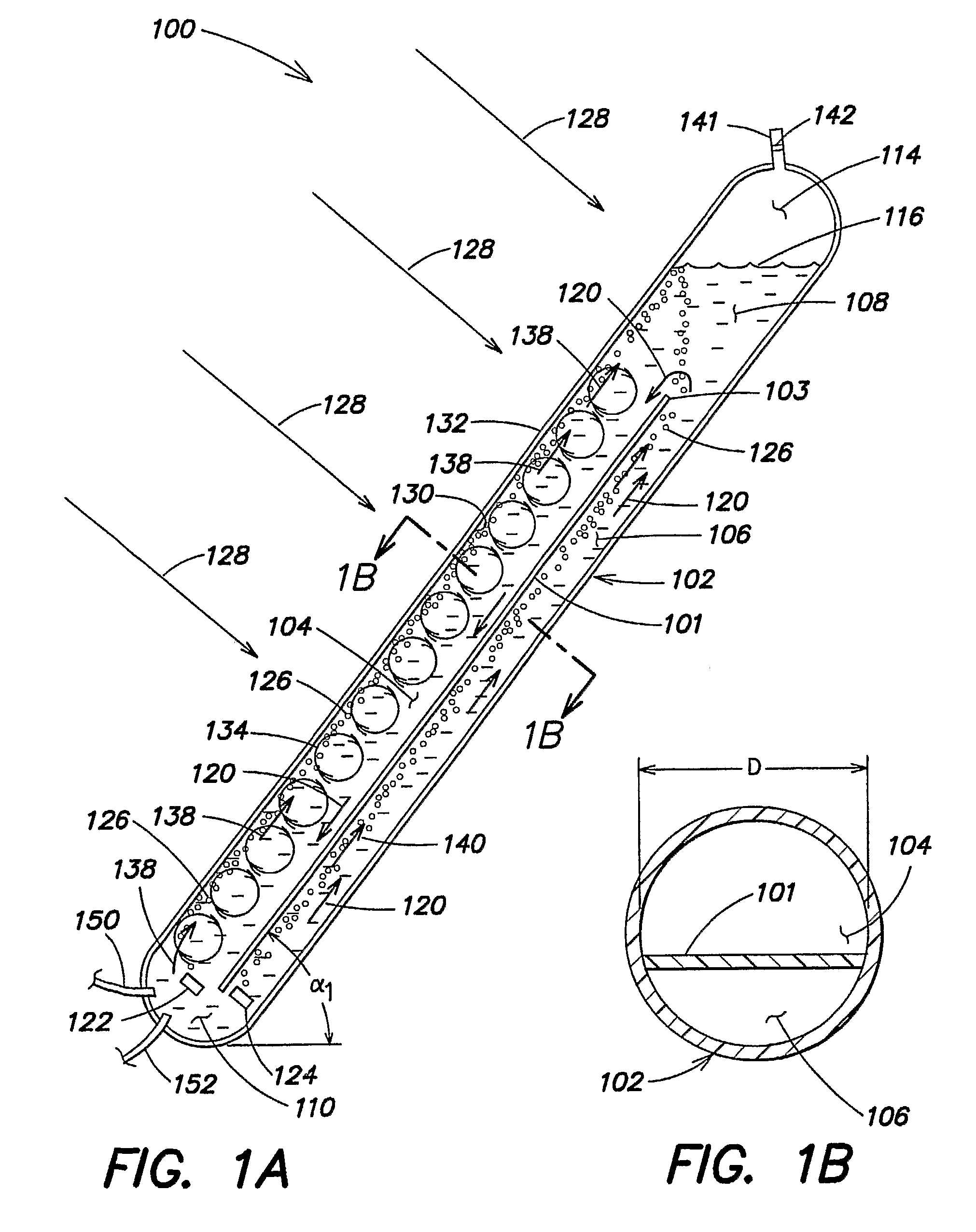
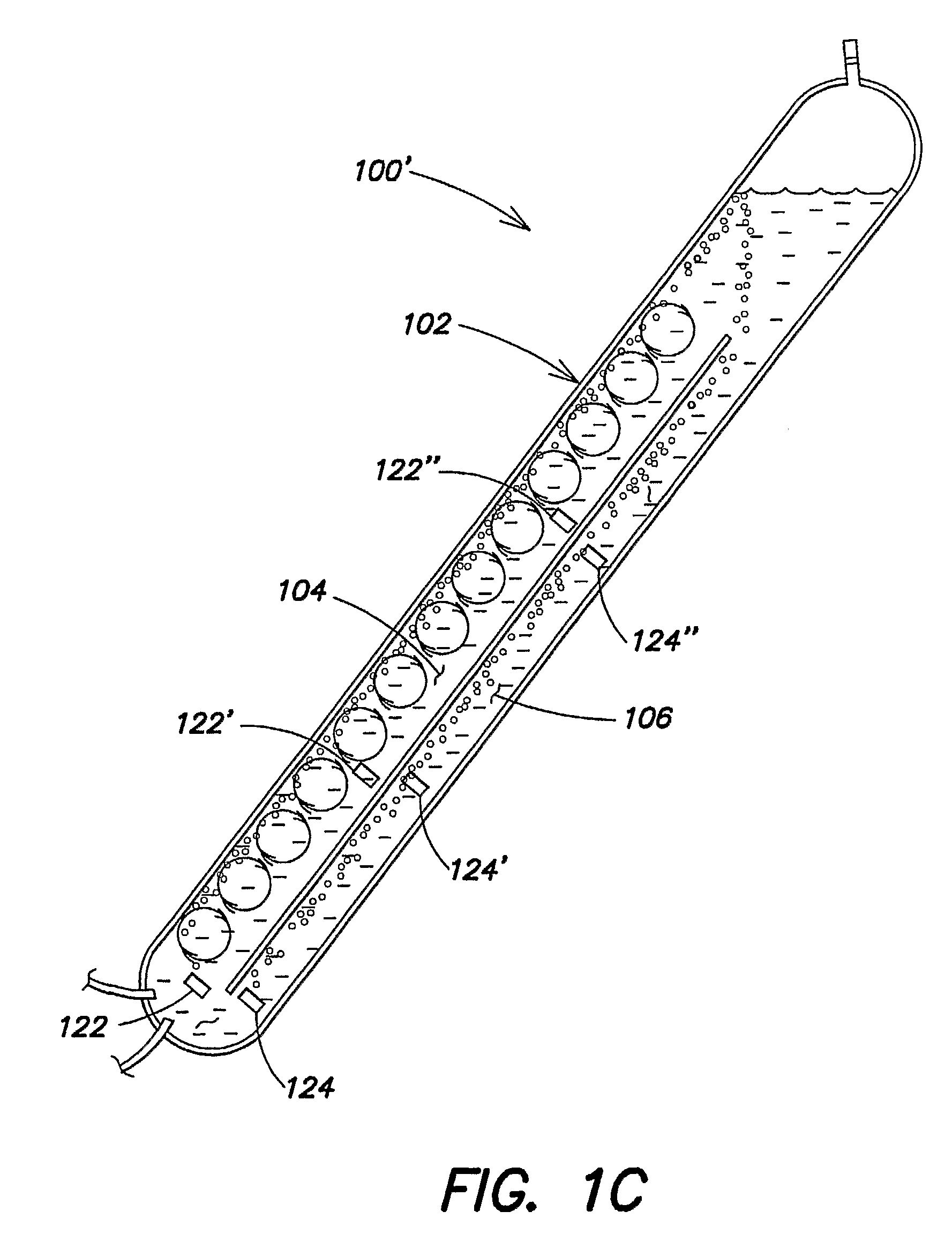
[0266]Four different photobioreactor systems were tested to investigate their algae production capabilities per photobioreactor footprint area. System 1 included an array of ten substantially triangular photobioreactors similar to those described in commonly owned PCT Publication No. WO 03 / 094598, incorporated herein by reference. System 1 included a solar panel conduits inclined at approximately 60 degrees relative to horizontal. Each conduit had an about 4 inch inner diameter and a length of about 9 feet 7 inches and the overall system had a working volume of approximately 900 liters. The reactors of system 1 had a total footprint area of about 1.435 m2. Each of systems 2-4 included a single conduit photobioreactor including a partition therein forming two channels, as described previously in the context of FIG. 1A, each conduit had a length ...

example 2

Mitigation of CO2 and NOx with a Three-Photobioreactor Module including Three Triangular Tubular Photobioreactors

[0272]Each photobioreactor unit of the module utilized for the present example comprised 3 tubes of essentially circular cross-section constructed from clear polycarbonate, assembled as shown in FIG. 1 of commonly owned PCT Publication No. WO 03 / 094598, with α1=about 45 degrees and α2=about 90 degrees. In this essentially triangular configuration, the vertical leg was about 2.2 m high and about 5 cm in inner diameter; the horizontal leg was about 1.5 m long and about 5 cm in inner diameter; and the hypotenuse was about 2.6 m long and about 10 cm in inner diameter. The photobioreactor module comprised 3 adjusted units arranged in parallel, similarly as illustrated in FIG. 2 of commonly owned PCT Publication No. WO 03 / 094598. This bioreactor module has a footprint of about 0.45 m2

[0273]A gas mixture (certified, AGA gas), mimicking flue gas composition was used (Hiroyasu et...

example 3

Mitigation of CO2 and NOx with a Photobioreactor Module including Thirty Triangular Tubular Photobioreactors

[0284]Each photobioreactor unit of the module utilized for the present example comprised 3 tubes of essentially circular cross-section constructed from clear polycarbonate, assembled as shown in FIG. 1 of commonly owned PCT Publication No. WO 03 / 094598, with α1=about 63 degrees and α2=90 degrees. In this essentially triangular configuration, the essentially vertical leg was 2.4 m high and 6.35 cm in diameter; the essentially horizontal leg was 1.22 m long and 5.08 cm in diameter; and the hypotenuse was 2.72 m long and 10.16 cm in diameter. The photobioreactor module comprised 30 adjusted units arranged in parallel, similarly as illustrated in FIG. 2 of commonly owned PCT Publication No. WO 03 / 094598. This bioreactor module has a footprint of about 3.72 m2

[0285]Gas input was via direct injection of flue gas from the Massachusetts Institute of Technology's (MIT's) Cogeneration ...


PUM

PropertyMeasurementUnit
internal volumeaaaaaaaaaa
wavelength rangeaaaaaaaaaa

Abstract

Certain embodiments of the invention involve methods and systems for preselecting, adapting, and preconditioning one or more species of photosynthetic organisms, such as algae, to specific environmental and / or operating conditions to which the photosynthetic organisms will subsequently be exposed during utilization in a photobioreactor apparatus of a gas treatment system. Also disclosed are new algal strains and cultures that can be produced by practicing the preselection, adaption, and preconditioning methods.

Description

RELATED APPLICATIONS[0001]This application is a continuation-in-part of U.S. patent application Ser. No. 11 / 106,695, now pending, filed Apr. 14, 2005, which claims the benefit of priority under Title 35, U.S.C. §119(e) of U.S. provisional application Ser. No. 60 / 562,057, filed Apr. 14, 2004, and which is a continuation-in-part of U.S. patent application Ser. No. 10 / 924,742, filed Aug. 23, 2004, now pending, which claims the benefit of priority under Title 35, U.S.C. §119(e) of U.S. provisional application Ser. No. 60 / 497,445, filed, Aug. 22, 2003, and which is a continuation-in-part of PCT International Application No. PCT / US03 / 15364 filed May 13, 2003, which was published under PCT Article 21(2) in English, which entered the U.S. national phase under 35 U.S.C. §371 and was assigned U.S. patent application Ser. No. 10 / 514,224, and which claims the benefit of priority via PCT / US03 / 15364 under Title 35, U.S.C. §119(e) of U.S. provisional application Ser. No. 60 / 380,179, filed May 13, ...

Claims


Application Information

Patent Timeline
Patent Type & Authority Patents(United States)
IPC IPC(8): C12N1/00C12M1/42C12M3/00A61L9/01C02F3/32C02F3/00C12M1/00
CPCB01D53/84B01D53/85C12M21/02C12M23/08C12M31/02C12M41/08B01D2251/95Y02W10/37Y02A50/20
Inventor BERZIN, ISAAC
Owner THE TRON GRP
Why Eureka
Try Eureka