
Wire electrode based ion guide device

a technology of ion guide and wire electrode, which is applied in the direction of particle separator tube details, separation processes, instruments, etc., can solve the problems of difficult to precisely fix them in space, and achieve the effects of efficient focus of ions, minimize the adverse impact of ion guide structure, and minimize capacitance between electrodes

Inactive Publication Date: 2013-08-13
SHIMADZU RES LAB SHANGHAI +1
View PDF21 Cites 10 Cited by
  • Summary
  • Abstract
  • Description
  • Claims
  • Application Information

AI Technical Summary

Benefits of technology

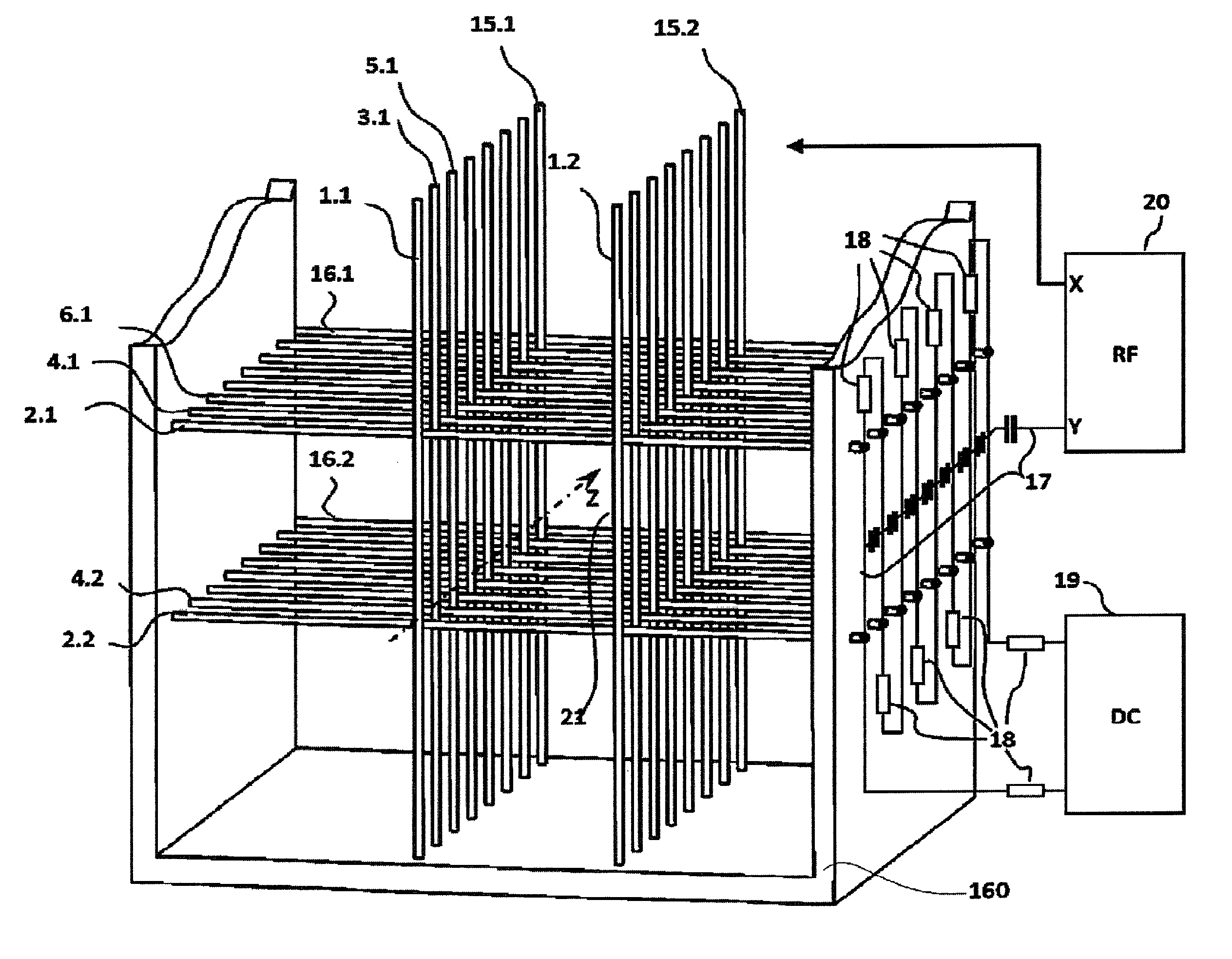
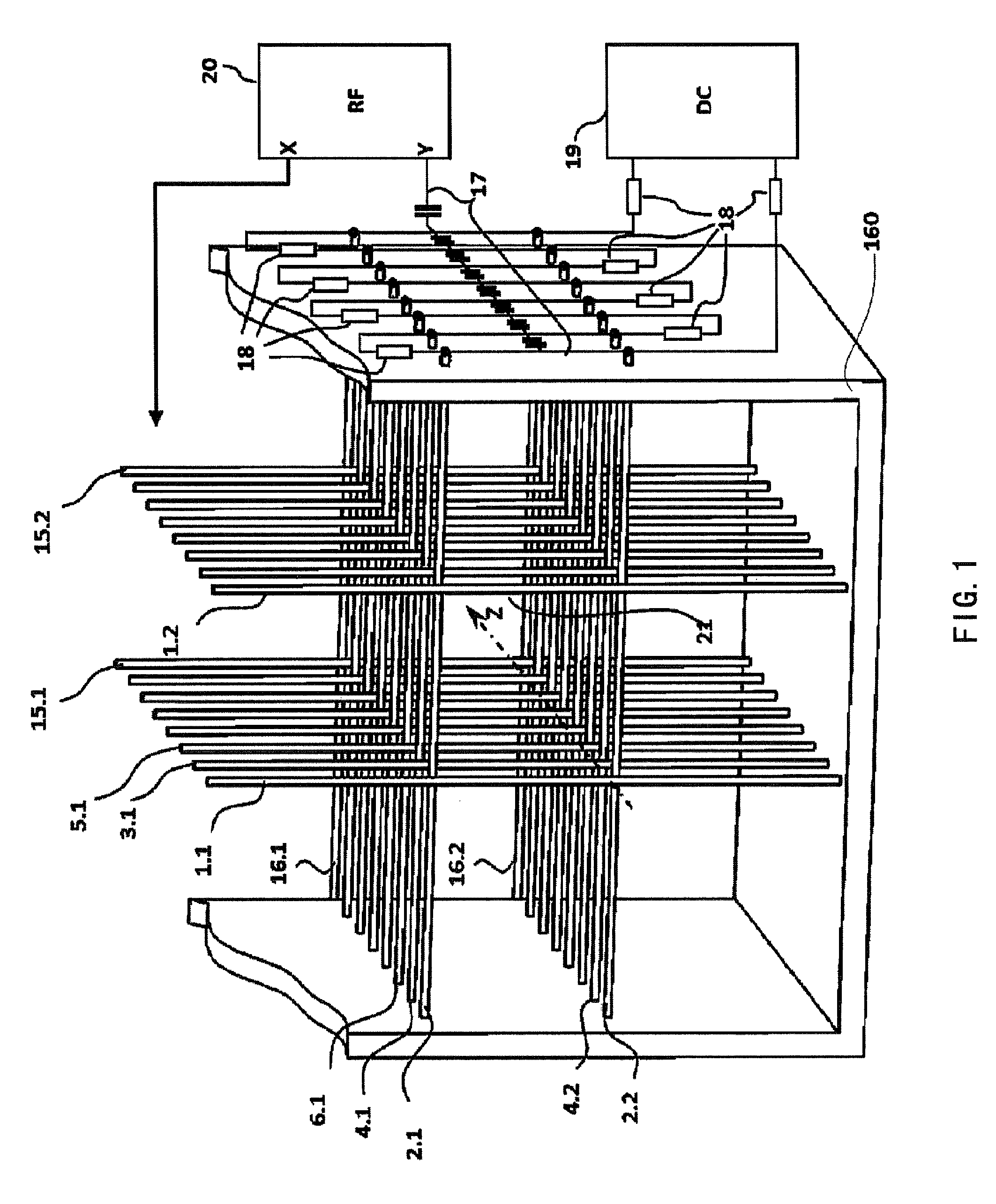
The invention design is an ion guide device that can efficiently focus ions at high pressure and high gas flow conditions in a low-vacuum region. The device should minimize the adverse impact of ion guide structure on the neutral gas flow and the capacitance between electrodes. One embodiment involves reducing the distance between wire electrodes and the ion guide axis to form a funnel type ion guide device for improving ion focusing effect and reducing the adverse effect of gas flow. Another embodiment involves using high voltage settings and potential gradient settings along the ion guide axis to effectively transmit the product ions, fragment ions, or desolvated ions. Gas flow exists in at least part of the ion guide device, and the pressure of the gas flow is between 10-10000 Pascal (0.075-75 Torrs). The diameter of the wire electrodes is kept less than 0.5 mm in order to reduce their impact on the gas flow. The wire electrodes can be fixed outside of the ion guide device using a fixed support or frame. Exhaust holes can be set on the outer wall of the frame to reduce the effect of gas flow.

Problems solved by technology

However, due to the lack of rigidity of the wire electrodes, it is difficult to precisely fix them in space.

Method used


Image

  • Wire electrode based ion guide device
  • Wire electrode based ion guide device
  • Wire electrode based ion guide device

Examples


Embodiment Construction

[0042]The present invention is more particularly described in the following examples that are intended as illustrative only since numerous modifications and variations therein will be apparent to those skilled in the art. Various embodiments of the invention are now described in detail. Referring to the drawings, like numbers indicate like components throughout the views. As used in the description herein and throughout the claims that follow, the meaning of “a”, “an”, and “the” includes plural reference unless the context clearly dictates otherwise. Also, as used in the description herein and throughout the claims that follow, the meaning of “in” includes “in” and “on” unless the context clearly dictates otherwise. Additionally, some terms used in this specification are more specifically defined below.

[0043]The terms used in this specification generally have their ordinary meanings in the art, within the context of the disclosure, and in the specific context where each term is used...


PUM


Abstract

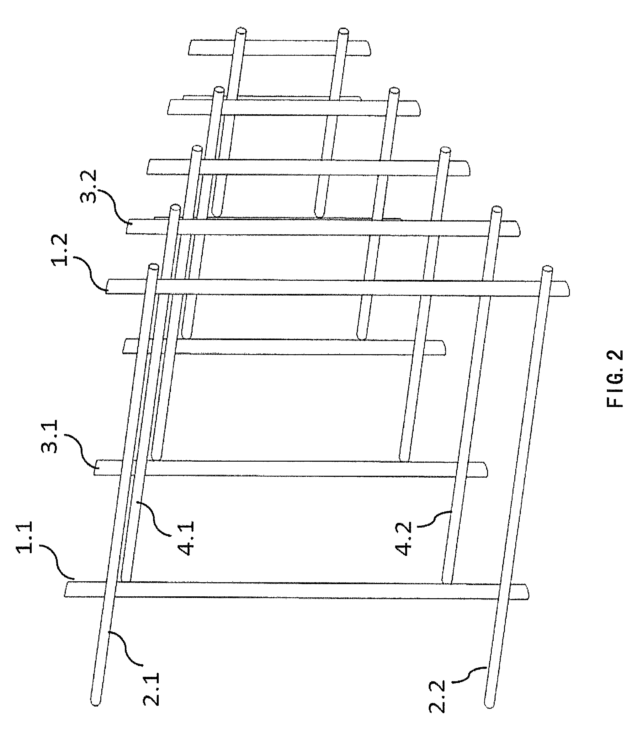
This invention presents a kind of ion guide device comprising multiple layers of stretched wire electrodes crossing in space. These wire electrodes are distributed along a defined ion guiding axis in the ion guide device. Each layer of wire electrodes contains at least two wire electrodes with some distance away from the guiding axis, and rotates with an angle relative to wire electrodes on neighboring layer. The ion guide contains multiple layers of wire electrodes to form a cage-like ion guide tunnel and keeps the mounting framework of those wire electrodes outside of the ion guide tunnel, thus reducing the interference of the gas flows from the ion guide device. A power supply provides voltage to each layer of wire electrodes, creates an electric field which focuses the ions towards the guiding axis.

Description

FIELD OF THE INVENTION[0001]This invention relates to an ion guide device, especially being capable of introducing ions from higher pressure (or low vacuum) environment into a low pressure environment for mass spectrometry analysis.BACKGROUND OF THE INVENTION[0002]In the field of mass spectrometry in order to introduce ions from ion source into mass analyzer at higher pressure (1˜104 Pa or 0.0075˜75 torrs), a high-frequency (or RF) guiding device is normally used. The effective potential barrier formed with the high frequency voltage applied on the electrodes in this device would accelerate ions towards the central axis for focusing. The ions will lose a large portion of their kinetic energy due to collisions with the neutral gas molecules, and hence ions would be confined in the vicinity of the central axis before passing through the aperture for differential pumping and entering into the lower pressure region of a mass spectrometer. This kind of RF focusing device has different va...

Claims


Application Information

Patent Timeline
Patent Type & Authority Patents(United States)
IPC IPC(8): H01J49/42H01J49/04H01J49/34
CPCH01J49/065H01J49/066
Inventor DING, LIJIANG, GONGYUSUN, WENJIAN
Owner SHIMADZU RES LAB SHANGHAI
Learn More