Centrifugal blood pumps with reverse flow washout

a centrifugal blood pump and reverse flow technology, which is applied in the direction of prosthesis, liquid fuel engine, therapy, etc., can solve the problems of pump stoppage, overloading the ability of the patient's natural heart, and external heart assist system components exposed to all sorts of accidents

Active Publication Date: 2013-09-17
JARVIK ROBERT
View PDF14 Cites 8 Cited by
  • Summary
  • Abstract
  • Description
  • Claims
  • Application Information

AI Technical Summary

Benefits of technology

[0011]1. It is an objective of the present invention to provide centrifugal and mixed flow blood pumps that are safe if turned off for at least three minutes.
[0013]3. Another objective is to provide centrifugal and mixed flow blood pumps that have rotors that are spun by the blood pressure gradient across the pumps when they are not powered, so that washing of all blood contacting surfaces is enhanced compared to pump rotors that don't spin when off.
[0014]4. An additional object of the invention is to provide centrifugal or mixed flow blood pumps that are both safe to turn off and are designed to cause minimal damage to the blood, including damage to blood cells, platelets, and breakage of large molecules into smaller fragments.
[0015]5. It is a still further objective of the present invention is to provide high reliability centrifugal and mixed flow blood pumps in which the impellers do not contact the pump housing when the power is turned off.
[0017]7. It is an object of the invention to employ triple or quadruple volute designs, having two or three splitter blades, in centrifugal or mixed flow blood pumps, to improve blood flow washing when the pumps are not powered.
[0018]8. It is also an object of the invention too provide centrifugal of mixed flow blood pumps having a restricted flow path cross sectional area and high enough resistance to prevent excessive flow regurgitation sufficient to cause sudden cardiac decompensation, loss of consciousness, and death, if the pump suddenly loses power.

Problems solved by technology

When patients are supported for many years their external heart assist system components are exposed to all sorts of accidents that should be viewed as inevitable.
The cable pulled free of the connector and the pump then stopped because it lost power.
If any rotary blood pump has high regurgitant flow, this will overwhelm the ability of the patient's natural heart to maintain sufficient forward flow pumped, and the patient will collapse and may die if the pump is not restarted immediately.
There is very little prior art dealing with rotary blood pumps adapted to be safe when turned off.
The patient's weakened natural heart will fail rapidly if the backflow is too much.
None of these pumps is safe when turned off even briefly in most patients, who quickly go into heart failure and may die.
But for patient safety it is not enough to limit the regurgitant flow to a value below 1 L / min.
Therefore, washout flow of the side of the pump chamber opposite the outlet is relatively poor and stagnant blood is subject to clotting.
There is so much friction that the rotor cannot be rotated by fluid forces, and the narrow gap regions between the rotor and casing will be especially susceptible to clotting.
This is unfortunate, because centrifugal blood pump designs have some particular advantages compared to axial flow pumps used for VADs.
Most centrifugal pumps use a single volute design that results in unbalanced lateral forces on the impeller bearings, due to the non-radial symmetry of the fluid forces.
This results from the non-symmetrical geometry of the pump volute.
This improves the washout of the impeller when the pump is stopped, but is not optimal.
If too many splitter blades are used, the flow channels become excessively restricted, cause excessive resistance, and may themselves become loci of thrombus.

Method used


Image

  • Centrifugal blood pumps with reverse flow washout
  • Centrifugal blood pumps with reverse flow washout
  • Centrifugal blood pumps with reverse flow washout

Examples


Embodiment Construction

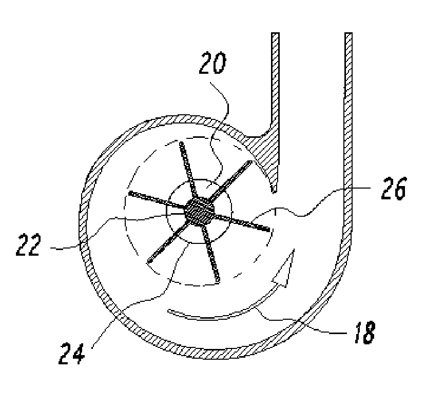
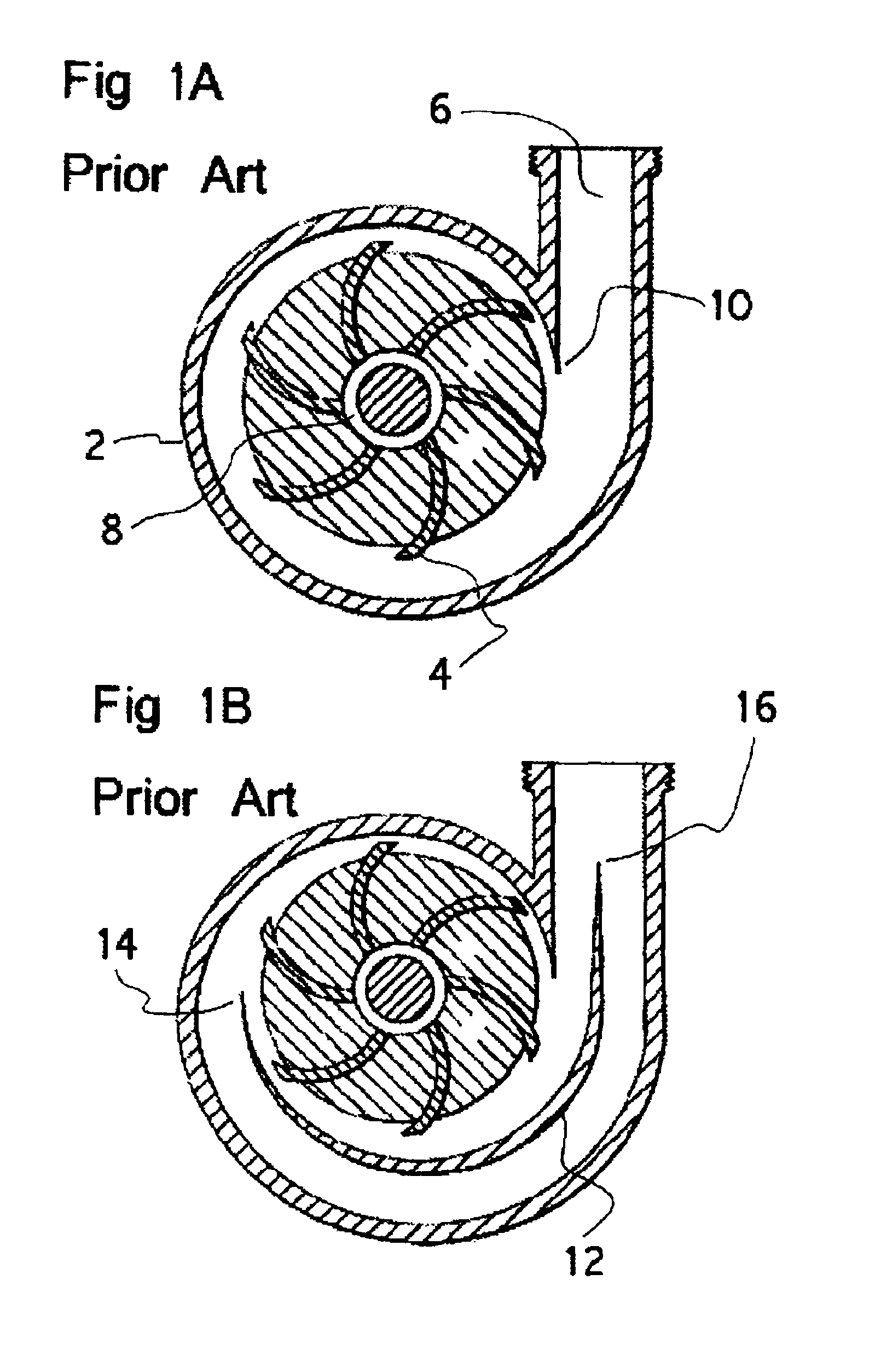
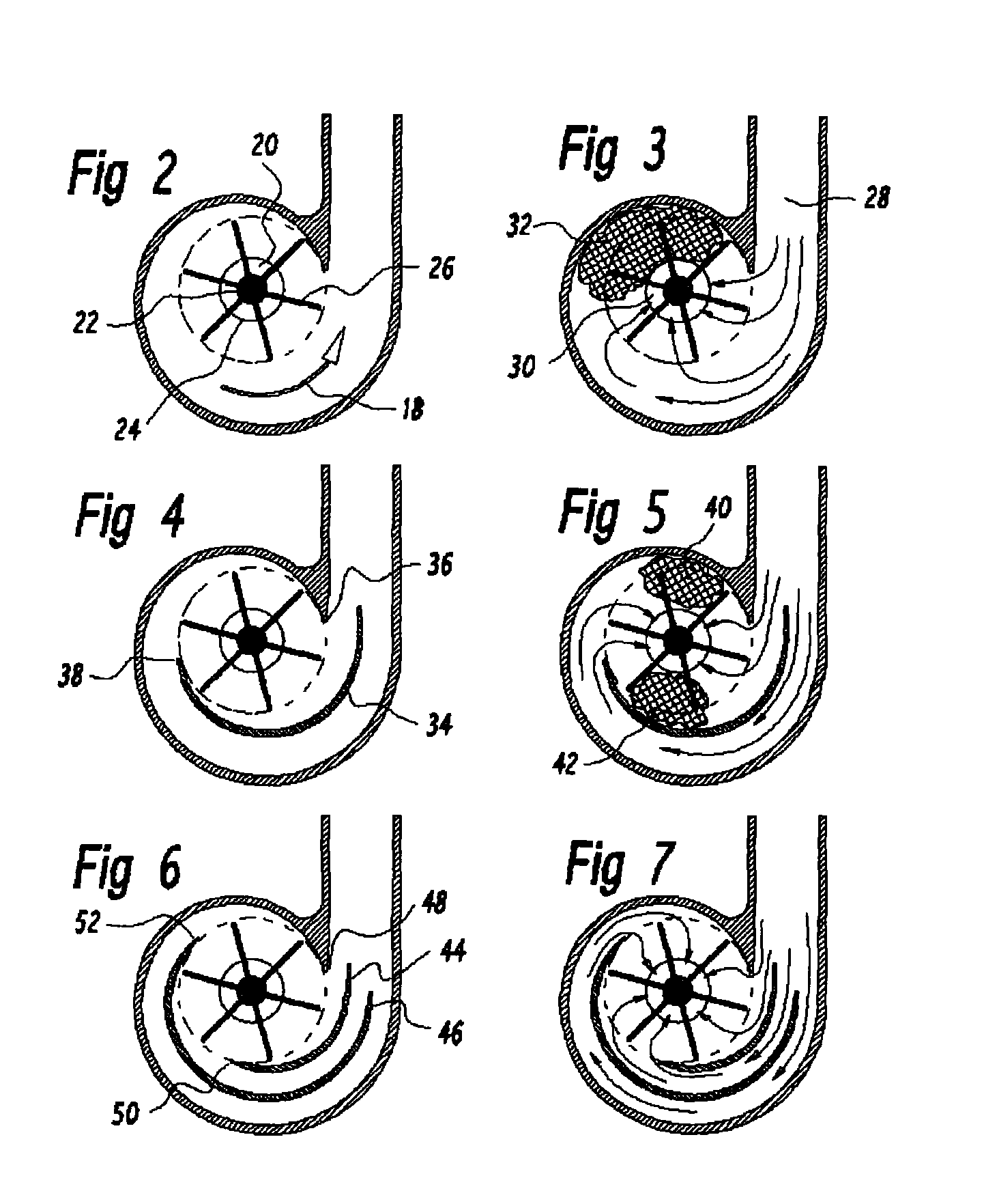
[0033]FIG. 1A shows the basic prior art structure of a centrifugal pump having a spiral casing 2, with an impeller 4, and volute that is comprised of the spiraling casing and tangential outflow tube 6. The flow enters centrally through an inflow opening 8, and exits tangentially through the outflow tube 6. As seen in FIG. 1A the impeller rotates counterclockwise, and it is seen that the fluid forced to the periphery of the casing by the action of the impeller proceeds along a channel of gradually enlarging cross-sectional area from the position known as the cutwater 10, to the outflow tube. In the prior art double volute centrifugal pump structure shown in FIG. 1B, a partition known as a splitter blade 12, divides the spiraling flow channel into two portions, each occupying approximately 180°. In the double volute design there are two cutwater structures, 14, 16, such that two flow channels are formed that join at the outflow tube.

[0034]In the single volute design flow proceeds unif...


PUM


Abstract

Blood pumps used as heart assist devices are commonly powered by an external battery and control system. If the external power is interrupted, such as by damaging an external cable, patients will have backflow across the pump. If the flow is too high, they may decompensate and die. If the backflow is relatively low, patients can survive until power is restored, but their blood pump must be sufficiently washed to prevent thrombus. Centrifugal blood pumps have been designed for good pumping performance, low blood damage, and avoidance of thrombus when they are running. The present invention recognizes the need to also provide enough washing to prevent thrombus when the pump power is turned off. The invention provides centrifugal pumps with triple or quadruple volute designs, or with axial flow impellers on the same shaft as the centrifugal pump impeller to help drive the rotor in reverse and enhance washing even with relatively low backflow. Also, in the preferred embodiment the centrifugal rotor is supported by low friction mechanical blood immersed bearings, to avoid contact of the rotor with the housing that creates small poorly washed crevices where thrombus can form.

Description

BACKGROUND[0001]Mechanical circulatory support has become widely applied in recent years. The number of patients treated with rotary blood pumps now exceeds the number of patients treated with heart transplant. Hydrodynamic rotary blood pumps include axial flow, mixed flow, centrifugal flow, and hybrid configurations. The mechanical principles of operation of these pumps have been developed, and their design and structure has largely been determined, by the need to meet the hemodynamic requirements of heart failure patients while avoiding excessive blood damage, and avoiding thrombus formation or bleeding resulting in the need for anticoagulation.[0002]The Jarvik 2000 is an axial flow ventricular assist device that has sustained patients for more than seven years. We have experience with more than 300 patient years of support. We have learned that patient safety is enhanced if the patient has enough residual pumping function of their natural heart to maintain life long enough to swi...

Claims


Application Information

Patent Timeline
Patent Type & Authority Patents(United States)
IPC IPC(8): A61M1/10A61M60/178A61M60/221A61M60/232A61M60/422A61M60/806A61M60/814A61M60/825
CPCA61M1/101F04D29/445F04D29/708A61M60/148A61M60/422A61M60/232A61M60/178A61M60/806A61M60/814A61M60/221A61M60/825
Inventor ROBERT, JARVIK
Owner JARVIK ROBERT
Why Eureka
Try Eureka