Light source employing laser-produced plasma

a laser-produced plasma and light source technology, applied in the field of light sources, can solve the problems of limited effectiveness, damage to the optics of euvl light sources, limited source lifetime, etc., and achieve the effect of reducing the generation of fast ions

Inactive Publication Date: 2013-09-17
RGT UNIV OF CALIFORNIA
View PDF17 Cites 2 Cited by
  • Summary
  • Abstract
  • Description
  • Claims
  • Application Information

AI Technical Summary

Benefits of technology

[0010]The present inventors have recognized that pre-pulses can be employed in generating LPPs such as, for example, Sn-based plasmas. Further, the present inventors have recognized that the use of such pre-pulses in generating LPPs can reduce the generation of fast ions from the LPPs, and thus can be useful in achieving longer-lasting light sources including, for example, EUVL light sources, EUV light sources for microscopy, pulsed laser deposition (PLD) particle sources and LPP x-ray sources.
[0011]In at least some embodiments of the present invention, a EUVL light source involving a LPP includes a standard main laser pulse together with an extra early laser pulse. The early laser pulse produces a pre-plasma with a finite density gradient. The pre-formed target plasma isolates the direct interaction of laser pulse with the sharp density jump at the target surface. More than 30 times reduction in ion kinetic energy is thus obtained with almost no loss of conversion efficiency (in terms of laser input to plasma emission). This is a higher reduction in ion energy than any existing techniques, and enables a large reduction in the amount of ablated material reaching the optics and other sensitive elements. Further, this enables the use of solid density targets (rather than requiring the use of complicated, expensive, or lower conversion efficiency low-density Sn-doped foam, fiber, or droplet targets). The cost of implementation is low, and the technique can be easily coupled into existing designs of laser plasma systems and / or EUVL systems, used in conjunction with existing Sn-doped droplet and low density foam targets, and / or used in combination with conventional methods to mitigate debris such as the use of buffer (or background or “stopping”) gas to restrict the movement / discharge of debris, or the use of electric fields to reduce debris output.

Problems solved by technology

Notwithstanding the promise of such light sources, a remaining significant problem in implementing EUVL light sources is the generation of energetic debris from the plasmas, which can damage the optics in a EUVL light source.
For example, while solid density tin targets offer the highest in-band conversion efficiency and the simplest target supply for high repetition rate operation, such targets result in high kinetic energy debris and subsequent optic damage that limits the source lifetime.
Nevertheless, all of these techniques suffer from serious drawbacks, including limited effectiveness (e.g., below industry requirements on ion dose to the optics), reduced conversion efficiency, and the addition of undesirable impurities and complexity.

Method used


Image

  • Light source employing laser-produced plasma
  • Light source employing laser-produced plasma
  • Light source employing laser-produced plasma

Examples


Embodiment Construction

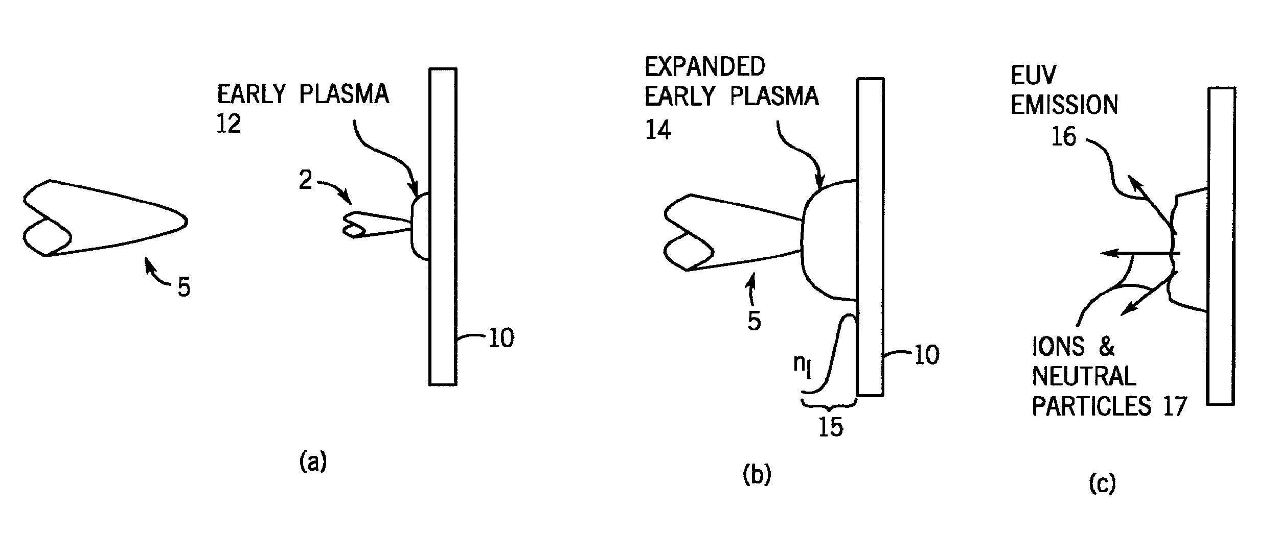
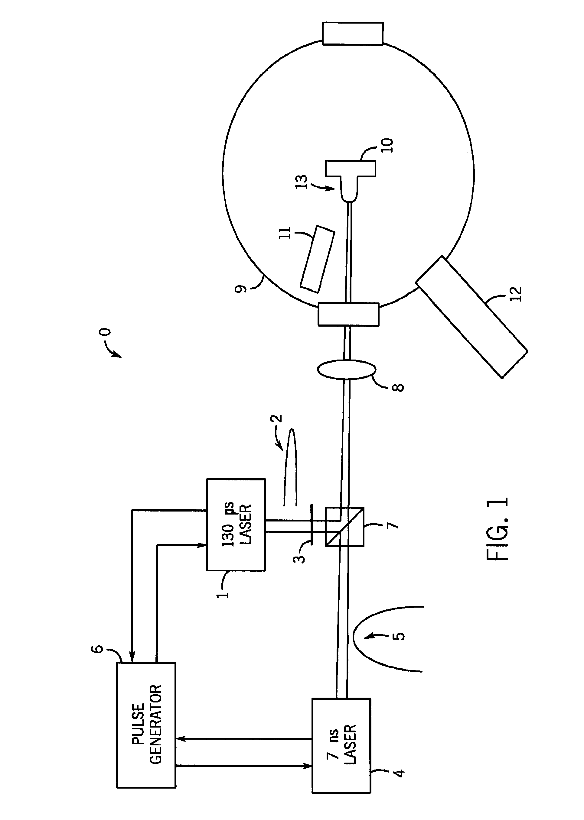
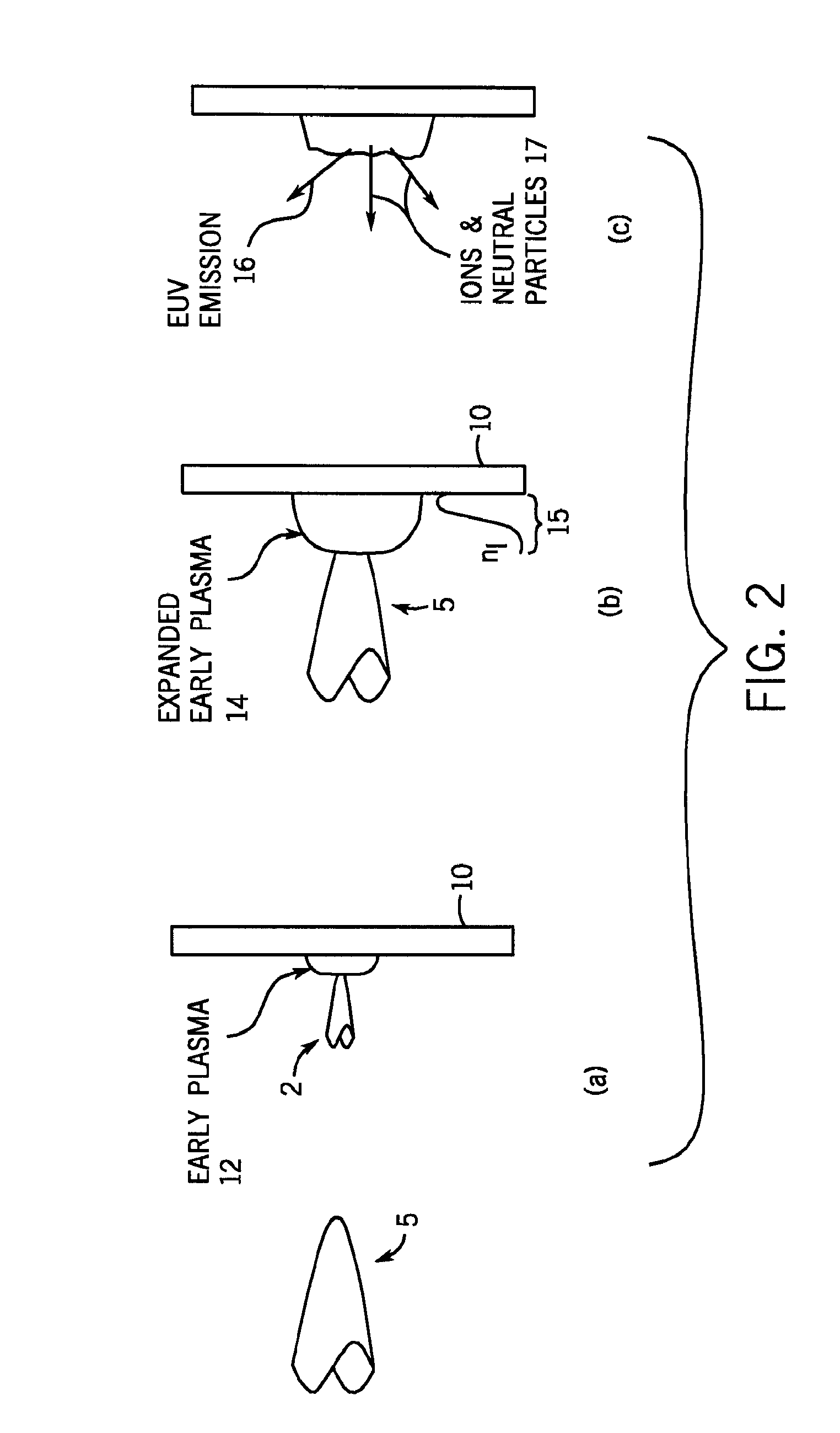
[0018]Referring to FIG. 1, a schematic diagram shows an exemplary extreme ultraviolet lithography (EUVL) light source 0 in accordance with at least some embodiments of the present invention, in which the light source involves generation of a laser-produced plasma (LPP) and is driven by dual pulses. More particularly, the light source 0 includes an “early pulse” or pre-pulse laser 1 that is capable of repeatedly emitting a sub-nanosecond, early laser pulse 2. The pre-pulse polarization of the pulse 2 is rotated with a waveplate 3. Additionally, the light source 0 includes a main laser 4 that is capable of repeatedly emitting a longer, main laser pulse 5 having a width of several nanoseconds. In the present embodiment, the lasers 1 and 4 are 1 micron solid-state Nd-YAG lasers, albeit other types of lasers can be used in other embodiments (e.g., other short-pulse laser systems, carbon dioxide lasers, etc.).

[0019]As will be described further below, typically the light source 0 is operat...


PUM


Abstract

A system and a method of generating radiation and / or particle emissions are disclosed. In at least some embodiments, the system includes at least one laser source that generates a first pulse and a second pulse in temporal succession, and a target, where the target (or at least a portion the target) becomes a plasma upon being exposed to the first pulse. The plasma expand after the exposure to the first pulse, the expanded plasma is then exposed to the second pulse, and at least one of a radiation emission and a particle emission occurs after the exposure to the second pulse. In at least some embodiments, the target is a solid piece of material, and / or a time period between the first and second pulses is less than 1 microsecond (e.g., 840 ns).

Description

CROSS-REFERENCE TO RELATED APPLICATIONS[0001]This application claims the benefit of U.S. provisional patent application No. 60 / 791,243 entitled “Improved Light Source Employing Laser-Produced Plasma” filed on Apr. 12, 2006, which is hereby incorporated by reference herein.STATEMENT REGARDING FEDERALLY SPONSORED RESEARCH OR DEVELOPMENT[0002]This invention was made with government support under DE-FG03-99ER54547 awarded by Department of Energy. The government has certain rights in this invention.FIELD OF THE INVENTION[0003]The present invention relates to light sources and, more particularly, to light sources involving the generation of laser-produced plasmas.BACKGROUND OF THE INVENTION[0004]In order to achieve higher density semiconductor circuits, it is desired that higher optical-resolution lithographic light sources be developed. Since resolution scales linearly with wavelength, many in the semiconductor industry view extreme ultraviolet lithography (EUVL) technology as a promisin...

Claims


Application Information

Patent Timeline
Patent Type & Authority Patents(United States)
IPC IPC(8): G21K5/00
CPCH05G2/001
Inventor TAO, YEZHENGTILLACK, MARK S.
Owner RGT UNIV OF CALIFORNIA
Why Eureka
Try Eureka