Frequency optimization using useful skew timing

Active Publication Date: 2013-09-17
AMPERE COMPUTING LLC
View PDF24 Cites 16 Cited by
  • Summary
  • Abstract
  • Description
  • Claims
  • Application Information

AI Technical Summary

Benefits of technology

[0013]Disclosed herein is a method for increasing the frequency of operation of the SoC, while minimizing the use of Low-Vt gates (cells). Low-Vt gates have a huge impact on the power, which sharply limits their use in the physical design of an IC (integrated circuit). An increase in the system frequency can be, but is not always, beneficial to the throughput of the

Problems solved by technology

Low-Vt gates have a huge impact on the power, which sharply limits their use in the physical design of an IC (integrated circuit).
An increase in the system frequency can be, but is not always, beneficial to the throughput of the sy

Method used


Image

  • Frequency optimization using useful skew timing
  • Frequency optimization using useful skew timing
  • Frequency optimization using useful skew timing

Examples


Example

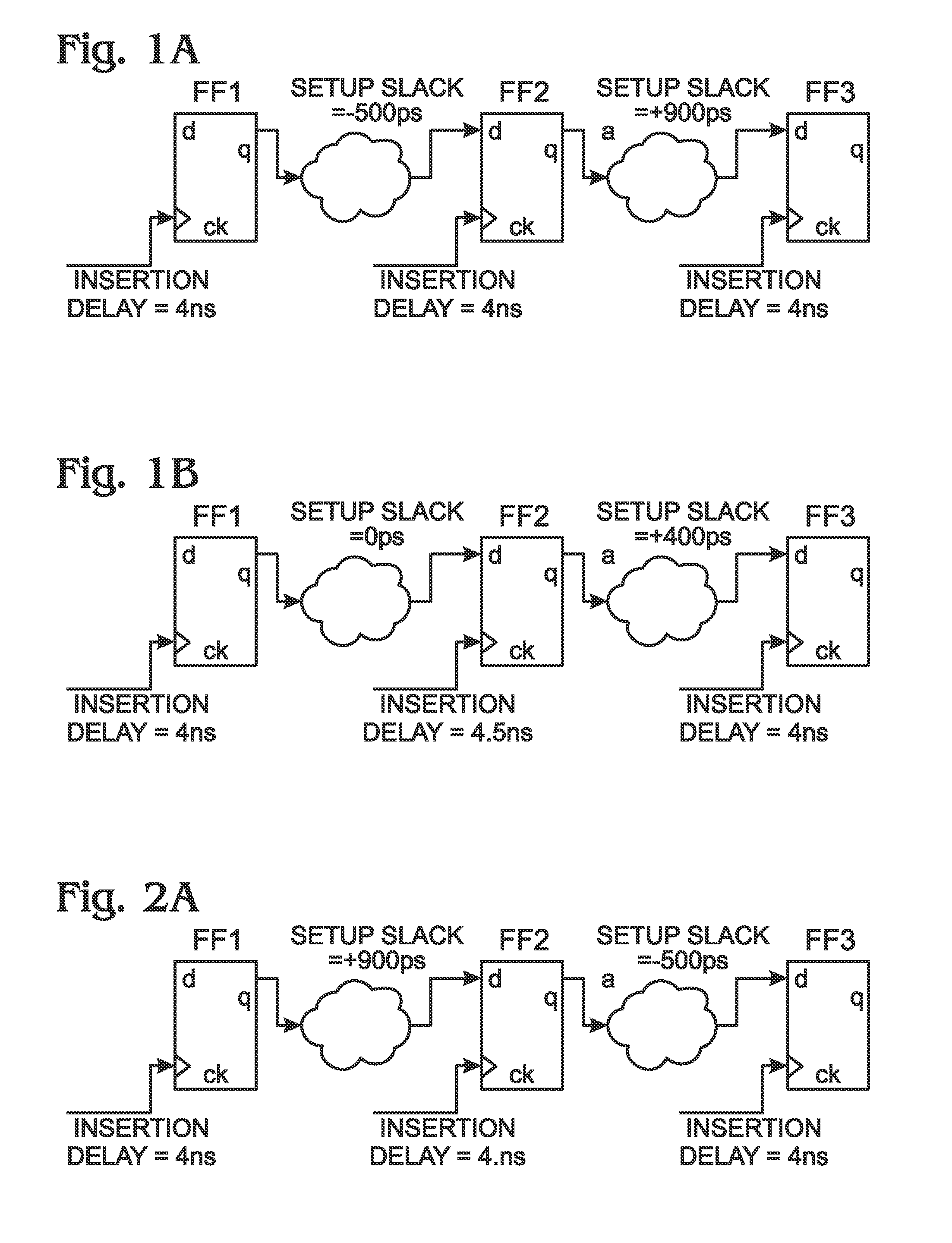
[0027]FIGS. 1A and 2B depict a delaying capture clock. Useful skew is sometime used by designers to close the timing in a system-on-chip (SoC). In this concept, the launch clock is advanced, or the capture clock is delayed, to meet the setup requirement of the design. As shown in FIG. 1A, the flop FF2 is violating setup slack by 500 picoseconds (ps) (shown as −500 ps) while the next stage flop FF3 is meeting the setup slack by 900 ps (shown as +900 ps). Since 900 ps is greater than 500 ps, the clock of flop FF2 can be delayed by 500 ps to meet the setup slack, as shown in FIG. 1B. This is called a delaying capture clock.

[0028]FIGS. 2A and 2B depict an advancing launch clock. As shown in FIG. 2A, FF3 is violating setup slack by −500 ps. However, the clock of flop FF2 can be advanced to meet the setup slack, as shown in FIG. 2B.

[0029]However, if positive slack (more than the absolute value of the negative slack) is not available in the preceding or the next stage of flops (e.g., 900 p...


PUM


Abstract

A circuit analysis tool is provided for optimizing circuit clock operating frequency using useful skew timing analysis. The instructions supply clock signal with an optimized operating frequency. A first gate signal input slack time is determined with respect to the clock signal to the first gate. If the first gate signal input has a negative slack time, a delay is added to the first clock signal. A second gate signal input slack time is determined with respect to the clock signal to the second gate. If the second gate signal input slack time is negative, a delay is added to the second clock signal necessary to create a second gate signal input positive slack time. In response to the first and second gate signal input positive slack times, it is determined that the circuit successfully operates at the clock optimized operating frequency.

Description

BACKGROUND OF THE INVENTION[0001]1. Field of the Invention[0002]This invention generally relates to signal networking and, more particularly, to a system and method for minimizing circuit leakage current while maximizing the clock operating frequency.[0003]2. Description of the Related Art[0004]The size, complexity, and operating or switching speeds of semiconductor ICs have increased, while feature geometries have decreased, and interconnect systems for such ICs have dramatically increased in complexity. In a digital circuit, data is suppose to move in lockstep, advancing one stage on each tick of the clock signal. This is enforced by synchronizing elements such as flip-flops or latches, which copy their input to their output when instructed to do so by the clock.[0005]As noted in Wikipedia, one approach that is used to analyze timing errors is to model the interconnect system as an arrangement of nets (interconnections between gate outputs and interconnected gate inputs) inter-cou...

Claims


Application Information

Patent Timeline
IPC IPC(8): G06F17/50
CPCG06F17/5031G06F30/3312
Inventor SINGLA, SUNIL KUMARPRABHAKAR, BALAJI
Owner AMPERE COMPUTING LLC
Why Eureka
Try Eureka