Semiconductor device
- Summary
- Abstract
- Description
- Claims
- Application Information
AI Technical Summary
Benefits of technology
Problems solved by technology
Method used
Image
Examples
embodiment 1
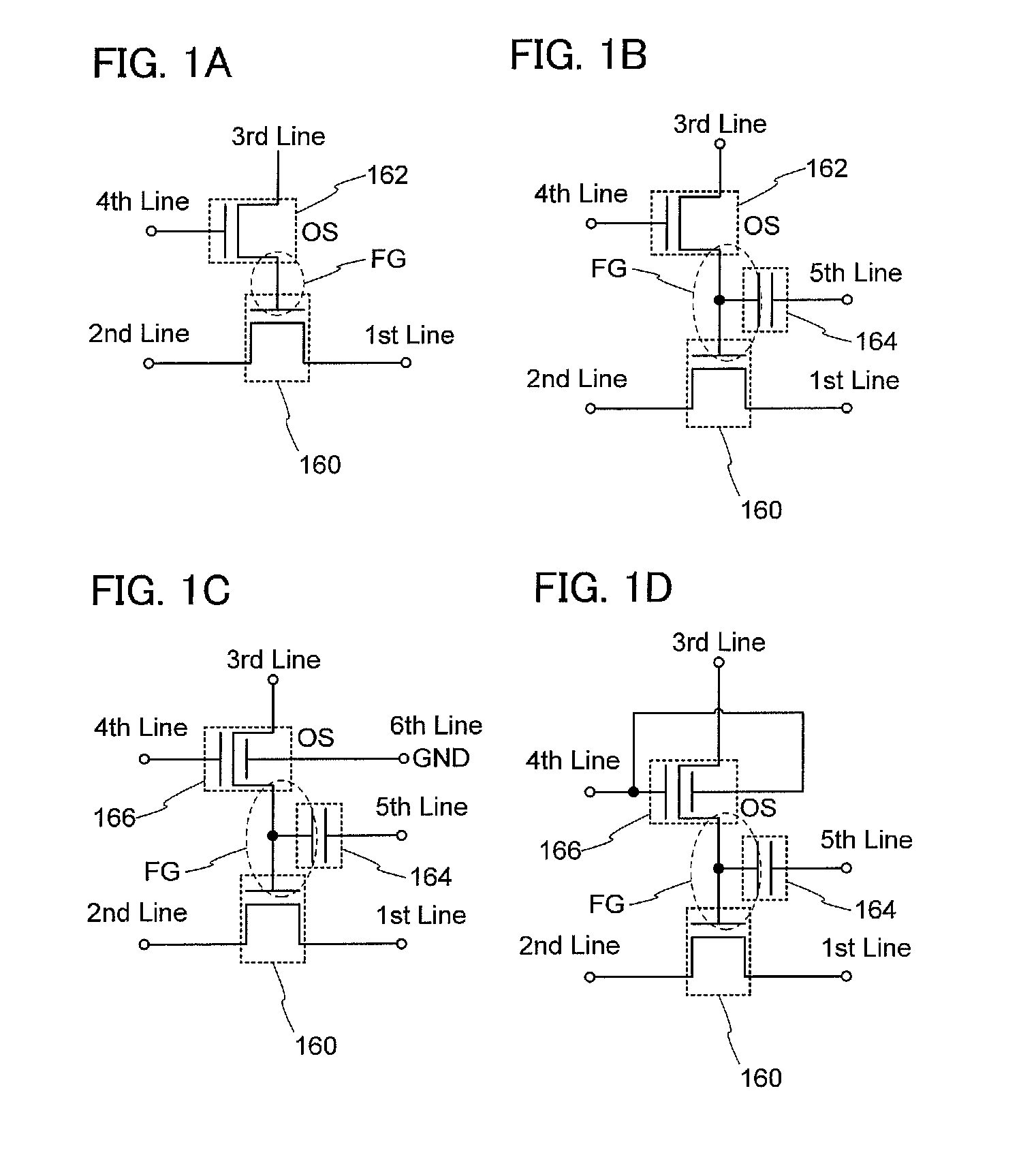
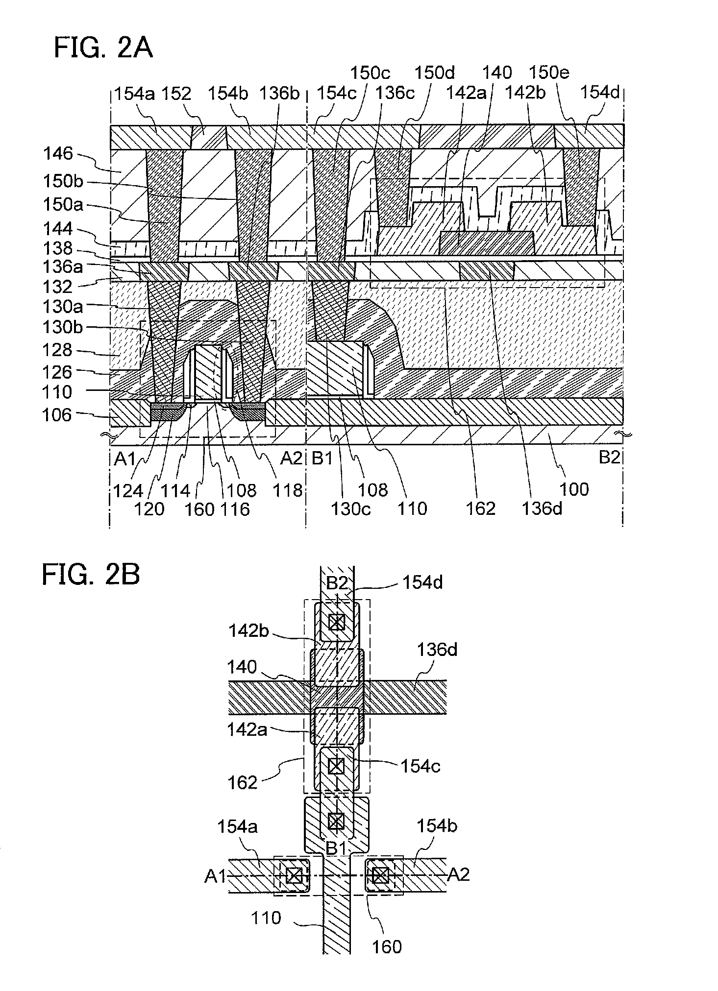
[0060]In this embodiment, structures and a manufacturing method of a semiconductor device according to one embodiment of the invention disclosed herein will be described with reference to FIGS. 1A to 1D, FIGS. 2A and 2B, FIGS. 3A to 3H, FIGS. 4A to 4G, FIGS. 5A to 5D, FIG. 6, FIGS. 7A and 7B, FIGS. 8A and 8B, FIG. 9, FIG. 10, FIGS. 11A and 11B, FIGS. 12A and 12B, FIGS. 13A and 13B, FIG. 22, and FIG. 23.
[0061]
[0062]In a semiconductor device illustrated in FIG. 1A, a gate electrode of a transistor 160 and one of a source electrode and a drain electrode of a transistor 162 are electrically connected to each other. A first wiring (a 1st line, also referred to as a source line) and a source electrode of the transistor 160 are electrically connected to each other. A second wiring (a 2nd line, also referred to as a bit line) and a drain electrode of the transistor 160 are electrically connected to each other. A third wiring (a 3rd line, also referred to as a first signal line) and the othe...
modification example
[0203]FIG. 10, FIGS. 11A and 11B, FIGS. 12A and 12B, and FIGS. 13A and 13B illustrate modification examples of structures of semiconductor devices. The semiconductor devices in each of which the transistor 162 has a structure different from that described above will be described below as modification examples. That is, the structure of the transistor 160 is the same as the above.
[0204]FIG. 10 illustrates an example of a semiconductor device including the transistor 162 in which the gate electrode 136d is placed below the oxide semiconductor layer 140 and the source / drain electrodes 142a and 1426 are in contact with a bottom surface of the oxide semiconductor layer 140. Note that the planar structure can be changed as appropriate to correspond to the cross section; therefore, only the cross section is shown here.
[0205]A big difference between the structure in FIG. 10 and the structure in FIG. 2A is the position at which the oxide semiconductor layer 140 is connected to the source / dra...
embodiment 2
[0232]In this embodiment, a circuit configuration and operation of a semiconductor device according to one embodiment of the present invention will be described.
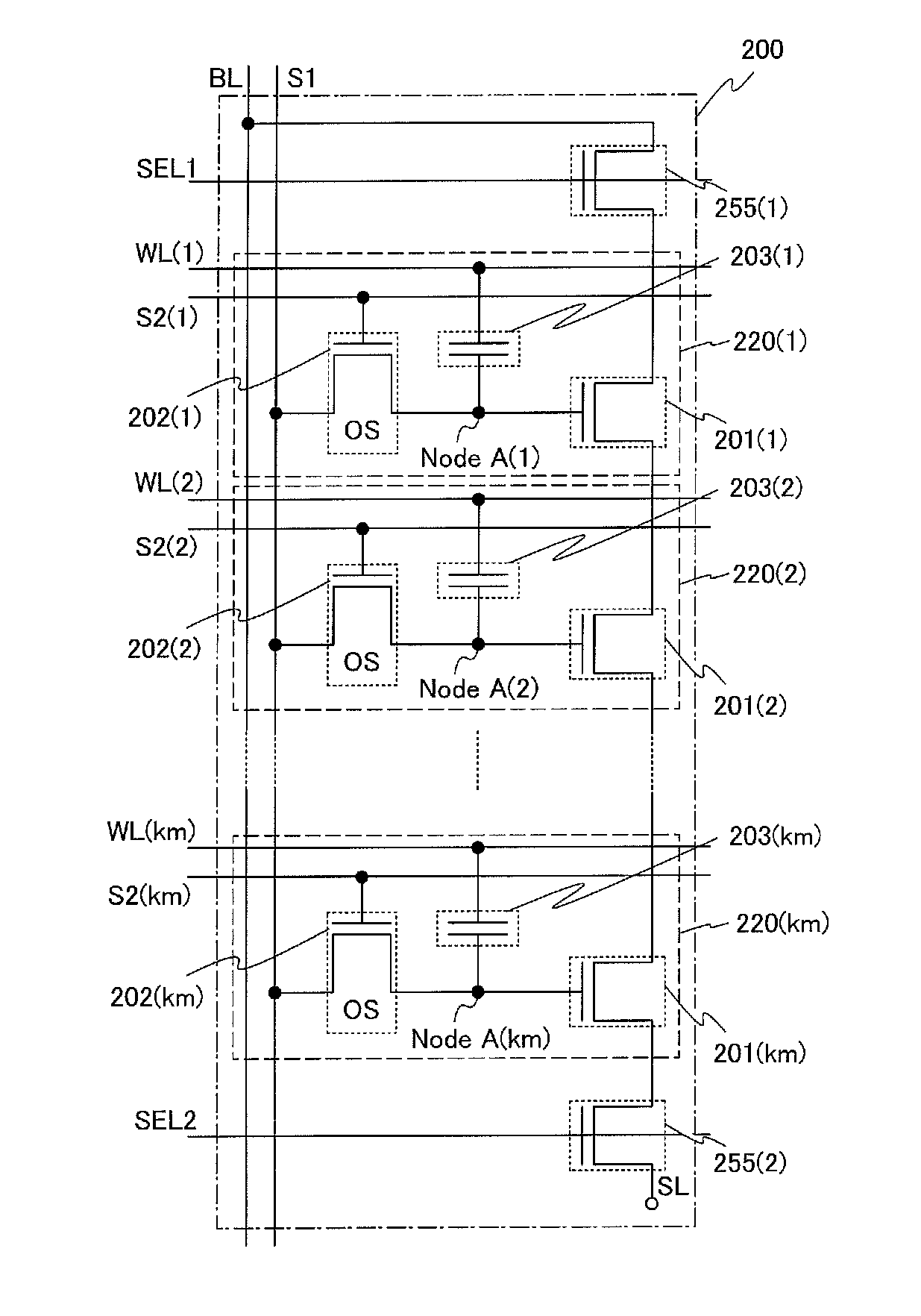
[0233]FIG. 14 illustrates an example of a circuit diagram of a semiconductor device (hereinafter also referred to as a NAND memory cell). Here, a NAND memory cell 200 in which memory cells 220 are connected in series is shown as an example.
[0234]The NAND memory cell 200 includes a plurality of memory cells 220(1) to 220(km) connected in series, km word lines WL(1) to WL(km), km second signal lines S2(1) to S2(km), a bit line BL, a source line SL, a first signal line S1, two selection lines SEL1 and SEL2, a transistor 255(1) placed between the bit line BL and the memory cell 220(1) along the selection line SELL, and a transistor 255(2) placed between the source line SL and the memory cell 220(km) along the selection line SEL2.
[0235]The memory cell 220(i) (i is an integer of any of 1 to km), which is one of the plurality of me...
PUM
 Abstract
Description
Claims
Application Information
 - R&D
- Intellectual Property
- Life Sciences
- Materials
- Tech Scout
- Unparalleled Data Quality
- Higher Quality Content
- 60% Fewer Hallucinations
Browse by: Latest US Patents, China's latest patents, Technical Efficacy Thesaurus, Application Domain, Technology Topic, Popular Technical Reports.
© 2025 PatSnap. All rights reserved.Legal|Privacy policy|Modern Slavery Act Transparency Statement|Sitemap|About US| Contact US: help@patsnap.com


